Method and apparatus for controlling power of a transmitted signal

a transmission signal and power technology, applied in the field of telecommunications, can solve the problems of significantly reducing the average transmit power, reducing the efficiency of multi-, and inherent high crest factor of multi-, so as to achieve the effect of increasing the average signal power, avoiding distortion and spectral regrowth, and increasing the signal gain

Inactive Publication Date: 2007-01-02
AVAGO TECH INT SALES PTE LTD
View PDF6 Cites 49 Cited by
  • Summary
  • Abstract
  • Description
  • Claims
  • Application Information

AI Technical Summary

Benefits of technology

[0008]The average signal power is increased without causing the power amplifier to enter the saturation region. Consequently distortion and spectral regrowth are avoided. To increase the average power of the transmitted signal, the signal for transmission is clipped to remove undesirably high peaks, and then the gain of the signal is increased. The clipping level and gain are adjusted based on the amount of determined interference. Accordingly, the clipping level is increased by, for example, the first amount when long term interference is determined, and increased, for example, by the second amount when short term interference is determined.

Problems solved by technology

A major challenge for an OFDM-based communication system is the inherent high crest factor (peak-to-average ratio) of multi-carrier systems.
The back-off for the power amplifier, however, reduces its efficiency.
Because the peak transmitted power is usually constrained by regulatory limits, a large back-off of the power amplifier design to deal with the high crest factor has the effect of significantly reducing the average transmit power.
The low average transmit power introduces several problems such as reducing radio coverage and making the transmitted signal more susceptible to interference.
However, as the number of sub-carriers increases, the coding rate slows and the coding process becomes more complicated (e.g. extensive computation, search, look-up tables).
However, inadequate clipping introduces excessive out-of-band distortion.

Method used


Image

  • Method and apparatus for controlling power of a transmitted signal
  • Method and apparatus for controlling power of a transmitted signal
  • Method and apparatus for controlling power of a transmitted signal

Examples


Embodiment Construction

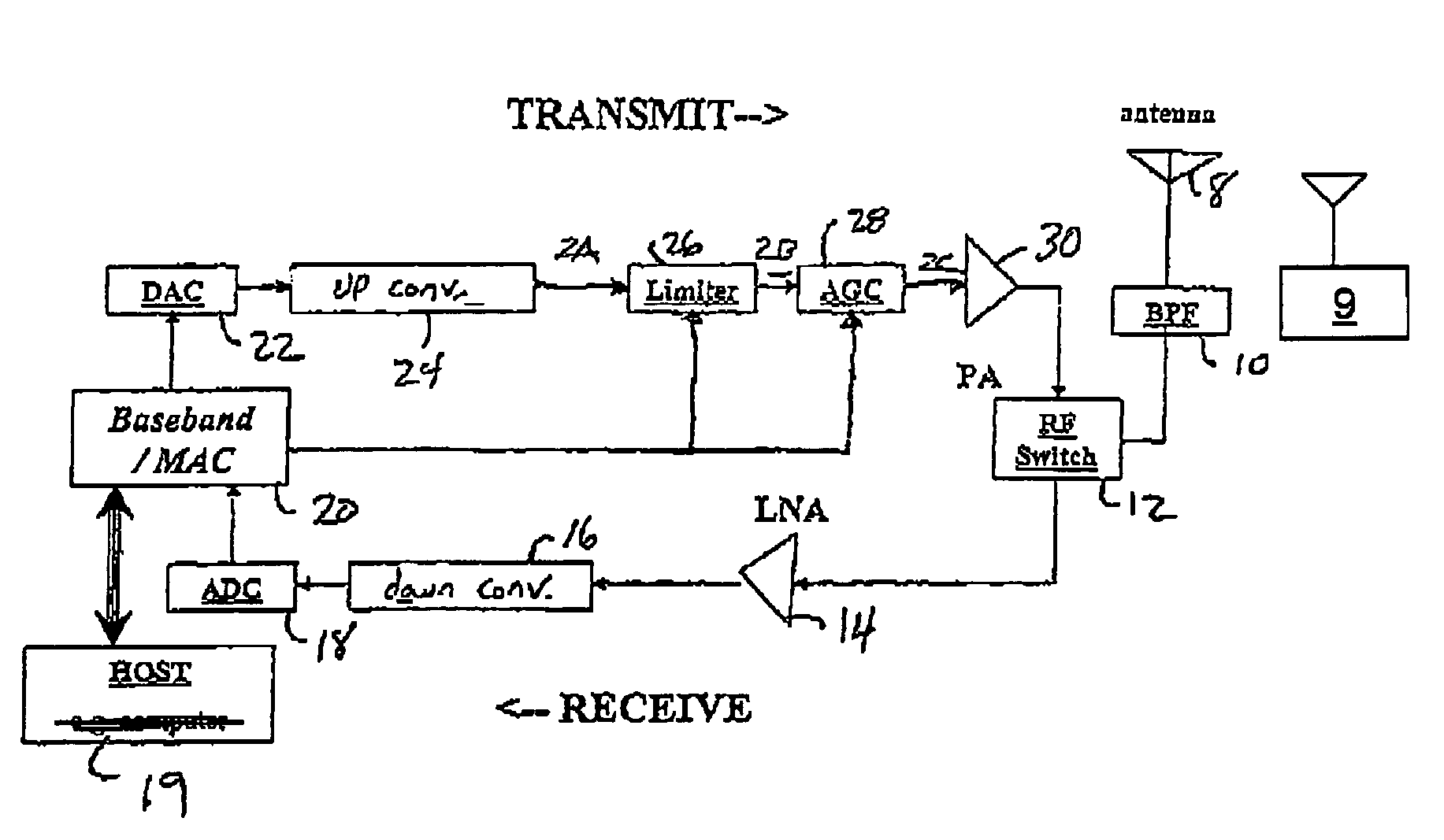
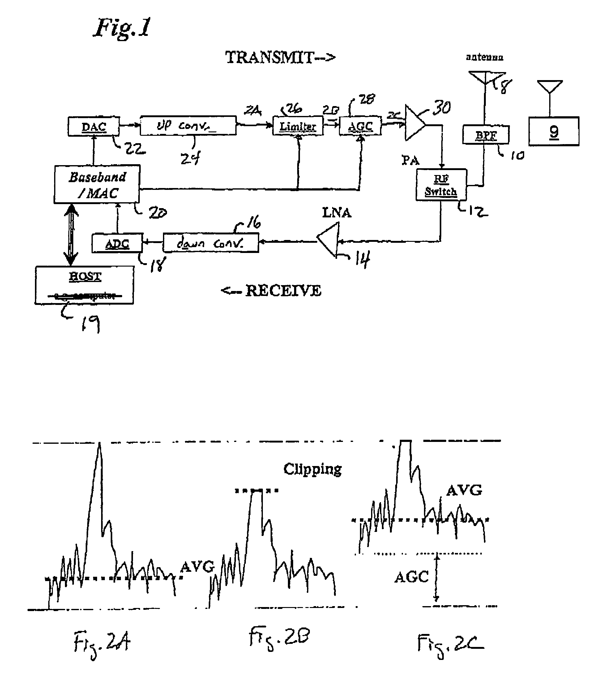
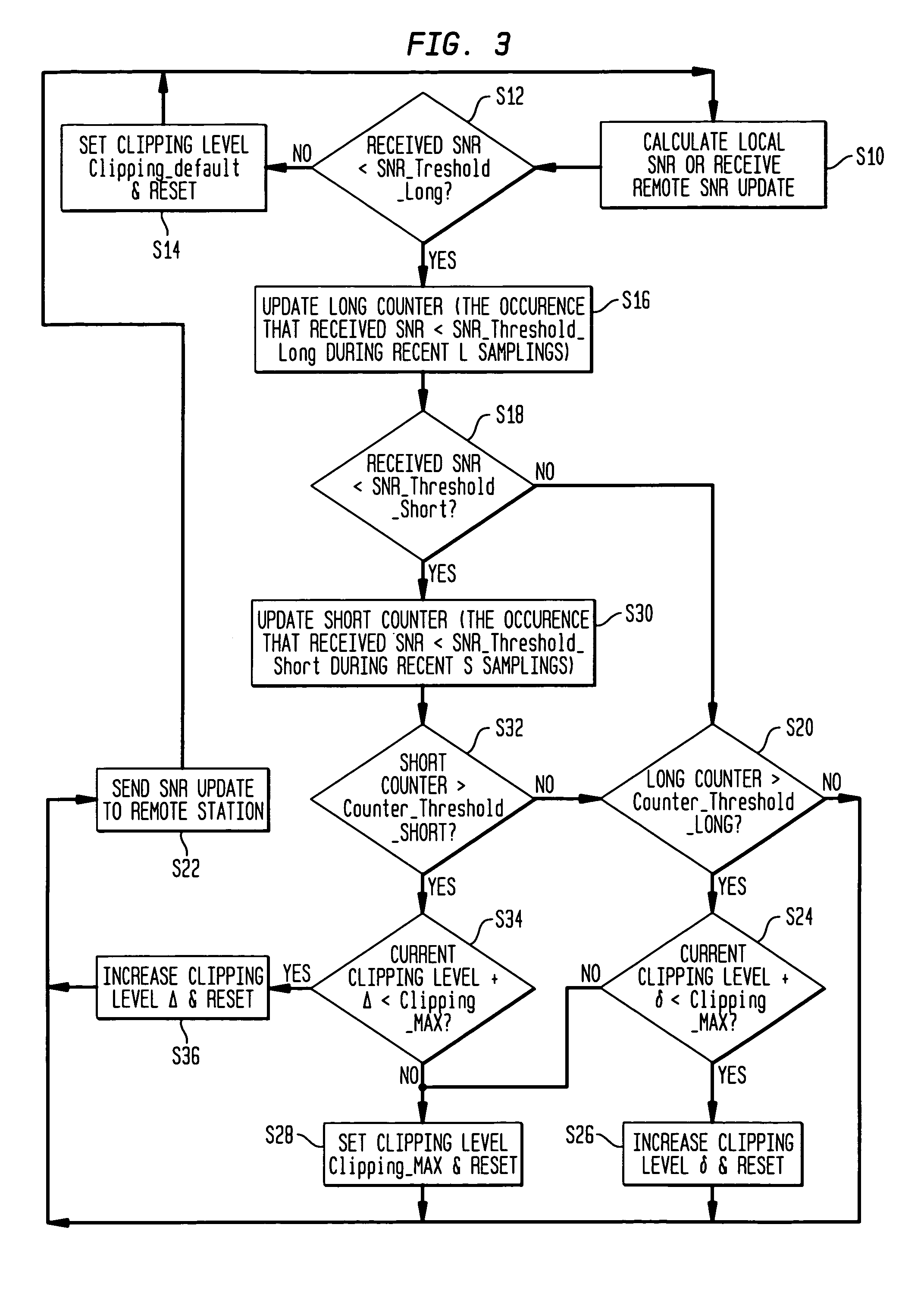
[0013]FIG. 1 illustrates a block diagram of a communication apparatus such as a wireless Local Area Network (LAN) card or base station employing the method of the present invention. While the method of the present invention will be described as implemented by a wireless LAN, the method is not limited to this implementation. For example, the method could be implemented by a cellular communication system.

[0014]As shown in FIG. 1, an antenna 8 receives and transmits signals to and from another transmission source 9 via a band-pass filter 10 and a duplexer 12. The duplexer 12 supplies the received signals to a low-noise amplifier 14. The amplifier 14 amplifies the signals and supplies them to a down converter 16, which down converts the radio frequency signal from the amplifier 14 to an intermediate frequency. An analog-to-digital converter (ADC) 18 converts the analog output of the down converter 16 to digital. A baseband / medium access controller (hereinafter “controller”) 20 receives...


PUM


Abstract

In the method and apparatus of controlling power of a transmitted communication signal, a communication signal is amplified and transmitted. At least one parameter on the transmitted signal is received, and a measure of interference with the transmitted signal is determined based on the received parameter. An average power level of the communication signal is increased by clipping the communication signal prior to amplification by an amount based on the determined measure.

Description

BACKGROUND OF THE INVENTION[0001]1. Field of the Invention[0002]The present invention relates to the field of telecommunications, and more particularly, a method and apparatus for controlling the power of a transmitted signal.[0003]2. Description of Related Art[0004]Orthogonal Frequency Division Multiplexing (OFDM) is a special form of multi-carrier modulation having inherent robustness against multipath effect. For example, IEEE 802.11a specifies the Physical Layer Entry for an OFDM system that provides a wireless Local Area Network (LAN) with data payload communication capabilities from 6 to 54 Mbits / sec in the Unlicensed National Information Infrastructure (U-NII) frequency band. The system uses 52 sub-carriers which are independently modulated by using Binary Phase Shift Keying (BPSK), Quadrature Phase Shift Keying (QPSK), 16-Quadrature Amplitude Modulation (16-QAM) or 64-Quadrature Amplitude Modulation (64-QAM) associated with different coding rate for different data speed.[000...

Claims


Application Information

Patent Timeline
Patent Type & Authority Patents(United States)
IPC IPC(8): H01Q11/12H04B7/00H04B7/005
CPCH04W52/24H04W52/225H04W52/52
Inventor BLAIR, JOHN L.HO, MING-JUKIM, DUKHYUNRAWLES, MICHAEL S.
Owner AVAGO TECH INT SALES PTE LTD
Why Eureka
Try Eureka