Electrode member for retinal stimulation, and artificial retinal device using the electrode member

a retinal stimulation and electrode member technology, applied in the field of electrode member for retinal stimulation and artificial retinal devices, can solve the problems of obliterating visual function, unable to find effective cures, and unable to achieve effective cures, and achieve the effect of convenient insertion

Inactive Publication Date: 2007-01-02
SUZUKI SATOSHI
View PDF11 Cites 29 Cited by
  • Summary
  • Abstract
  • Description
  • Claims
  • Application Information

AI Technical Summary

Benefits of technology

[0012]According to the first invention, the positioning projection of the support comes into contact with the retina when the electrode member for retinal stimulation is attached over the retina. Consequently, the effect of press against a part of the retina stimulated by the electrode can be reduced as compared with the case where the overall underside of the support comes into contact with the retina as in the prior art.
[0017]According to the second invention, since a single construction serves both as the positioning projection and as the fixing portion, the construction of the electrode member for retinal stimulation can be simplified as compared with the case where both are provided so as to project individually.
[0022]According to the fourth invention, an adverse effect of pressing the retina can be reduced since the positioning projection is provided. Furthermore, an image more approximate to an actual one can be formed since the needle-shaped electrodes transmit the electric signals directly to the retinal bipolar cells.
[0040]Tissues (for example, cornea) in the front of the eyeball are not necessarily left for a person undergoing an operation for implanting in an eyeball the artificial retina device described in each of the eighth to eleventh inventions. Accordingly, the front of the eyeball can be opened so that an opening is formed. In this surgical manner, the artificial retina device can easily be inserted.

Problems solved by technology

No effective cure has yet been found for loss of sight in spite of recent development in medical technique.
Loss of sight is not only a mere obliteration of visual function but also it affects a patient's spiritual life and social life.
In this case, since the electrode member 100 is fixed over the retina while the overall underside of the support 102 is in contact with the retina, there is a possibility that the underside of the support may press the retina, adversely affecting the retina.

Method used


Image

  • Electrode member for retinal stimulation, and artificial retinal device using the electrode member
  • Electrode member for retinal stimulation, and artificial retinal device using the electrode member
  • Electrode member for retinal stimulation, and artificial retinal device using the electrode member

Examples


first embodiment

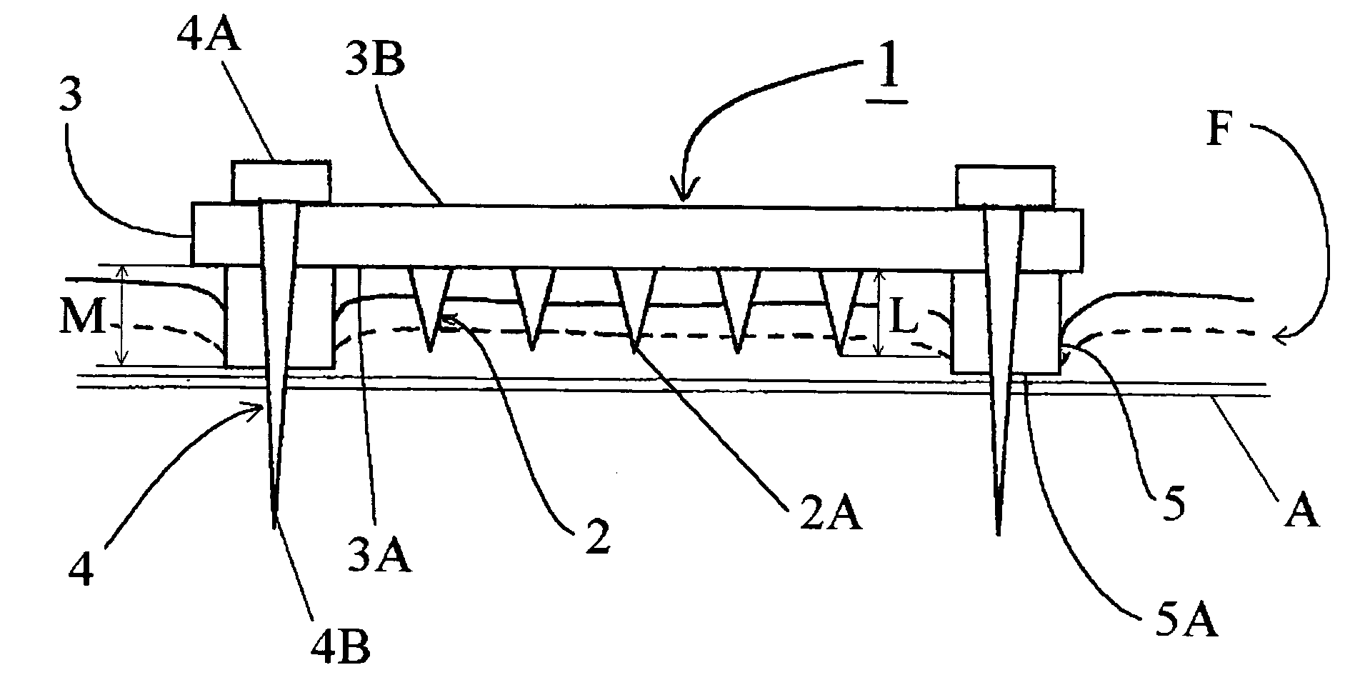
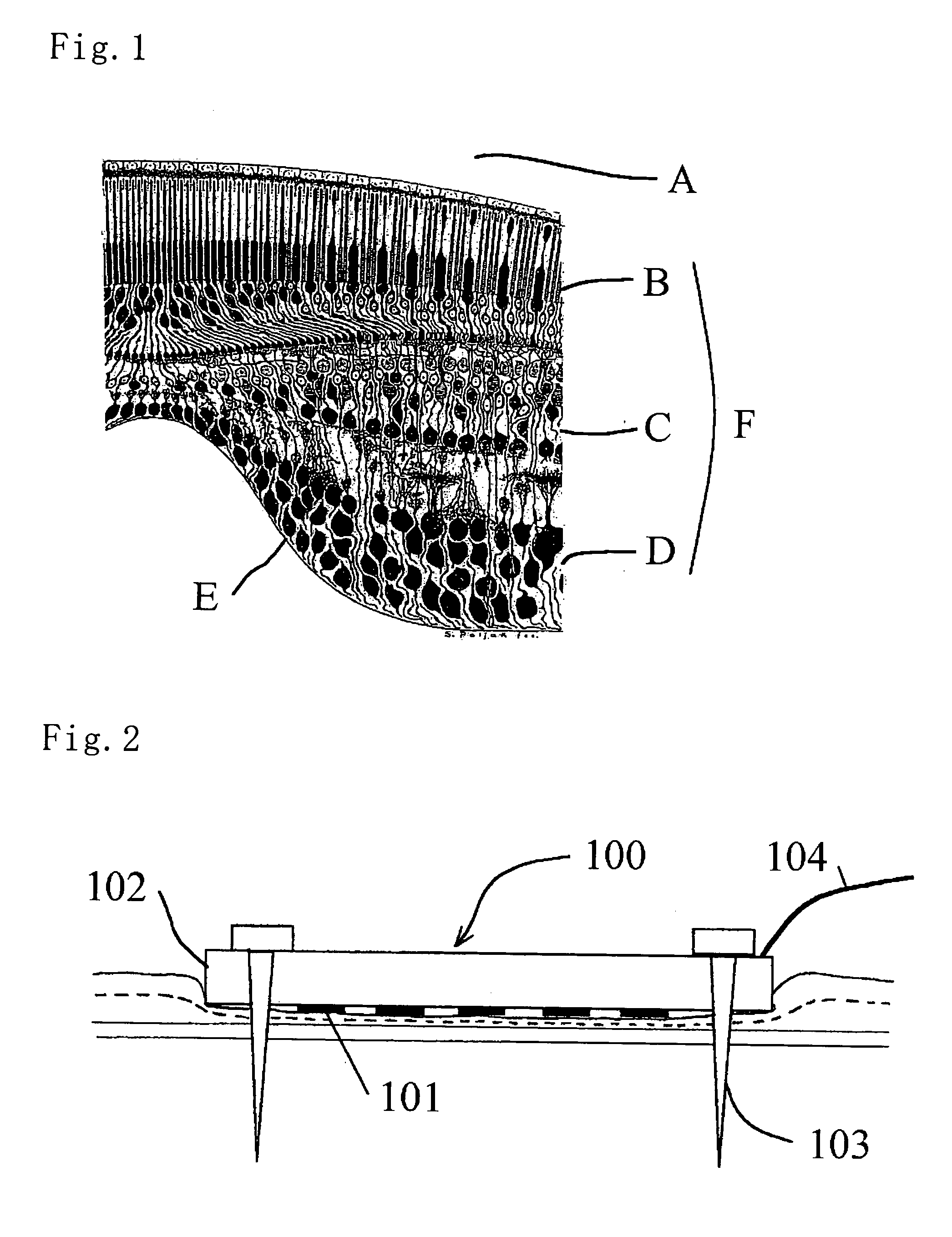
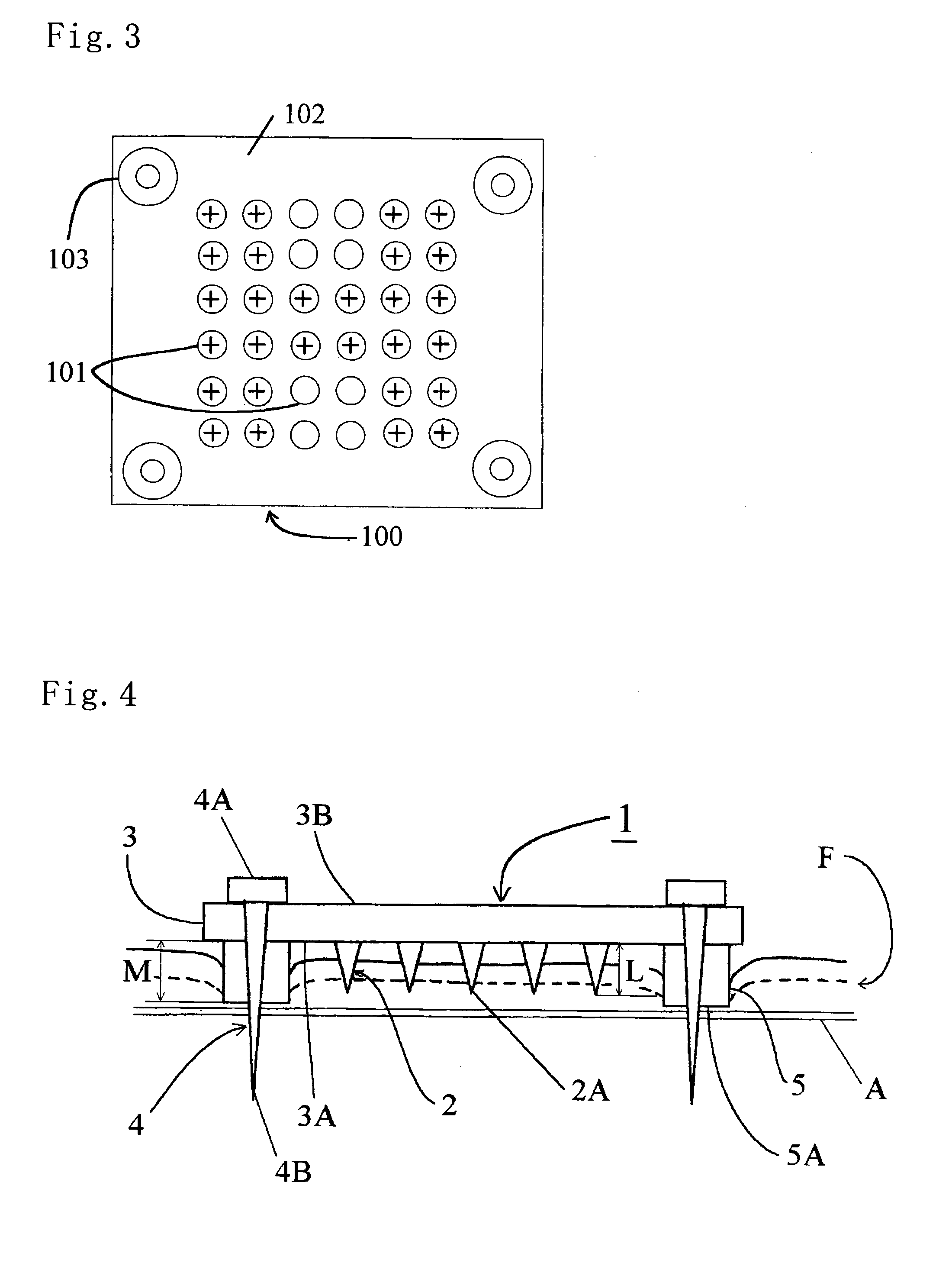
[0059]A first embodiment will be described with reference to FIGS. 1 to 8. FIG. 1 is a side sectional view of a retina F of a healthy person. The sclera A is located outside the retina F and covers an outer face of the eyeball. Inside the sclera A are photoreceptors B, retinal bipolar cells C and retinal ganglion cells D sequentially in this order. The electrode member 1 for retinal stimulation of the embodiment (hereinafter referred to as “electrode member 1”) is expected to be applied to patients of Retinitis Pigmentosa and age-related macular degeneration (ARMD). In symptoms of these patients, photoreceptors B are degenerated such that light cannot be converted to electric signals. Next, a visual path such as the retinal bipolar cells C and retinal ganglion cells D fails to function, which failure results in loss of sight. However, it is known that about 70% of the retinal bipolar cells C and about 30% of the retinal ganglion cells D are left in a patient heavily suffered from Re...

second embodiment

[0072]A second embodiment will be described with reference to FIGS. 9 to 11. Firstly, the arrangement of the second embodiment will be described with reference to FIG. 11. The artificial retina device 10 comprises the electrode member 1 and the signal transmitting section 11. Both members 1 and 11 are connected to each other by the electric wire W. The artificial retina device 10 is designed to be attached to an inner part of the eyeball G. The signal transmitting section 11 is a receiver which receives image-forming electric signals from a transmitter 12 provided outside the eyeball G, by a radio system. The signal transmitting section 11 has an outer diameter which ranges from about 5 mm to about 8 mm and is substantially as large as or slightly larger than an inner diameter of a crystal lens H. A signal control device 13 (including for example, a CCD camera, microcomputer, etc.) is connected to the transmitter 12 for generating and controlling image signals.

[0073]In order that th...

third embodiment

[0075]A third embodiment will be described with reference to FIGS. 12 to 16. Firstly, the arrangement of the second embodiment will be described with reference to FIG. 14. The artificial retina device 20 comprises the electrode member 1, the signal transmitting section 21 transmitting electric signals to the electrode member 1, a control device 22 (including a microcomputer) controlling the electric signals and a fixing section 23. The signal transmitting section 21 is a receiver which receives image-forming electric signals from a transmitter 24 provided outside the eyeball G, by a radio system. The control device 22 includes a control circuit 25 and a power supply device 26. The power supply device 26 is a secondary cell such as a lithium cell. The fixing section 23 is provided for fixing the electrode member 1 to the retina (the construction thereof will be described in detail later). The fixing section 23 also serves as a coil to supply to the power supply device 26 a power supp...


PUM


Abstract

An object is to provide an electrode member for retina stimulation which can form an actually transmitted image without pressing the retina in an excessively broad range and to provide an artificial retina device using the electrode member. An electrode member includes electrodes disposed in a shape of a vertical and horizontal matrix, a support holding each electrode at a predetermined position, and a fixing pin fixing four corners of the support to a sclera. Each electrode projects in the shape of a needle from an opposed face of the support toward a retina. The fixing pin is provided with a positioning projection allowing a distal end of each electrode to come into contact with retinal bipolar cells and limiting the overall opposed face to come into contact with a retina when the support is fixed to the retina.

Description

TECHNICAL FIELD[0001]The present invention relates to an electrode member for retinal stimulation, and an artificial retina device or the like using the electrode member.DESCRIPTION OF BACKGROUND ART[0002]No effective cure has yet been found for loss of sight in spite of recent development in medical technique. Loss of sight is not only a mere obliteration of visual function but also it affects a patient's spiritual life and social life. Accordingly, a technique for curing the loss of sight has been desired.[0003]FIG. 1 is a sectional view of a retina. A sclera A forming an outer layer of an eyeball is outside a retina. Inside the sclera are photoreceptors B, retinal bipolar cells C and retinal ganglion cells D sequentially in this order. Of these, the photoreceptors B serve to receive light and convert it to an electric signal. The retinal bipolar cells C and retinal ganglion cells D serve to transmit the electric signal to the brain. Light incident in front of the eyeball (from do...

Claims


Application Information

Patent Timeline
Patent Type & Authority Patents(United States)
IPC IPC(8): A61N1/05A61F2/14A61N1/36
CPCA61F2/14A61N1/0543A61N1/36046
Inventor SUZUKI, SATOSHI
Owner SUZUKI SATOSHI
Why Eureka
Try Eureka