Device for fixing a gas showerhead or target plate to an electrode in plasma processing systems

a technology of plasma processing system and shower head, which is applied in the direction of plasma technique, vacuum evaporation coating, coating, etc., can solve the problems of reducing the the showerhead, insufficient thermal conductance between the showerhead or the electrode, and non-uniform gas distribution below the showerhead, so as to improve the contact surface area. , the effect of improving the temperature uniformity of the showerhead

Inactive Publication Date: 2007-01-09
ANELVA CORP
View PDF6 Cites 54 Cited by
  • Summary
  • Abstract
  • Description
  • Claims
  • Application Information

AI Technical Summary

Benefits of technology

[0017]An object of the present invention is to provide a device for fixing a gas showerhead or target to a RF or DC electrode in plasma processing systems, being capable of improving the thermal conductance from the showerhead or target to the RF or DC electrode and improving the gas distribution below the showerhead.
[0033]A technique is invented to fix the showerhead or target to the RF or DC electrode by using magnetic force, which increases the contact-surface-area between the showerhead or target with the electrode, and eliminates the formation of thin-gas-reservoir between the electrode and the showerhead. This improves the temperature uniformity of the showerhead or target and gas distribution below the showerhead.
[0034]In accordance with the embodiments of the present inventions, since it is possible to fix the showerhead or target to the RF or DC electrode by using magnetic force, the contact-surface-area between the showerhead or target with the electrode can be increased, and the formation of thin-gas-reservoir between the electrode and the showerhead can be eliminated. Therefore, the embodiments can improve the temperature uniformity of the showerhead or target and gas distribution below the showerhead.

Problems solved by technology

This method of fixing poses two major problems.
The first problem is insufficient thermal conductance between the showerhead or target and the electrode, and the second problem is non-uniform gas distribution below the showerhead.
This causes two problems.
The first problem is the reduction of thermal conductance between the showerhead 105 and the top electrode 101.
Because non-uniform temperature on the showerhead 105 changes the chemistry of process gas below the showerhead 105, it adversely affects the process on the wafer surface.
This matter results in non-uniform etch rate on the surface of the wafer 115.
Even though the above two problems are explained using a dry etching reactor, the same problems exist in most of the other plasma assisted wafer processing reactors with or without the magnetic field assistance.

Method used


Image

  • Device for fixing a gas showerhead or target plate to an electrode in plasma processing systems
  • Device for fixing a gas showerhead or target plate to an electrode in plasma processing systems
  • Device for fixing a gas showerhead or target plate to an electrode in plasma processing systems

Examples


first embodiment

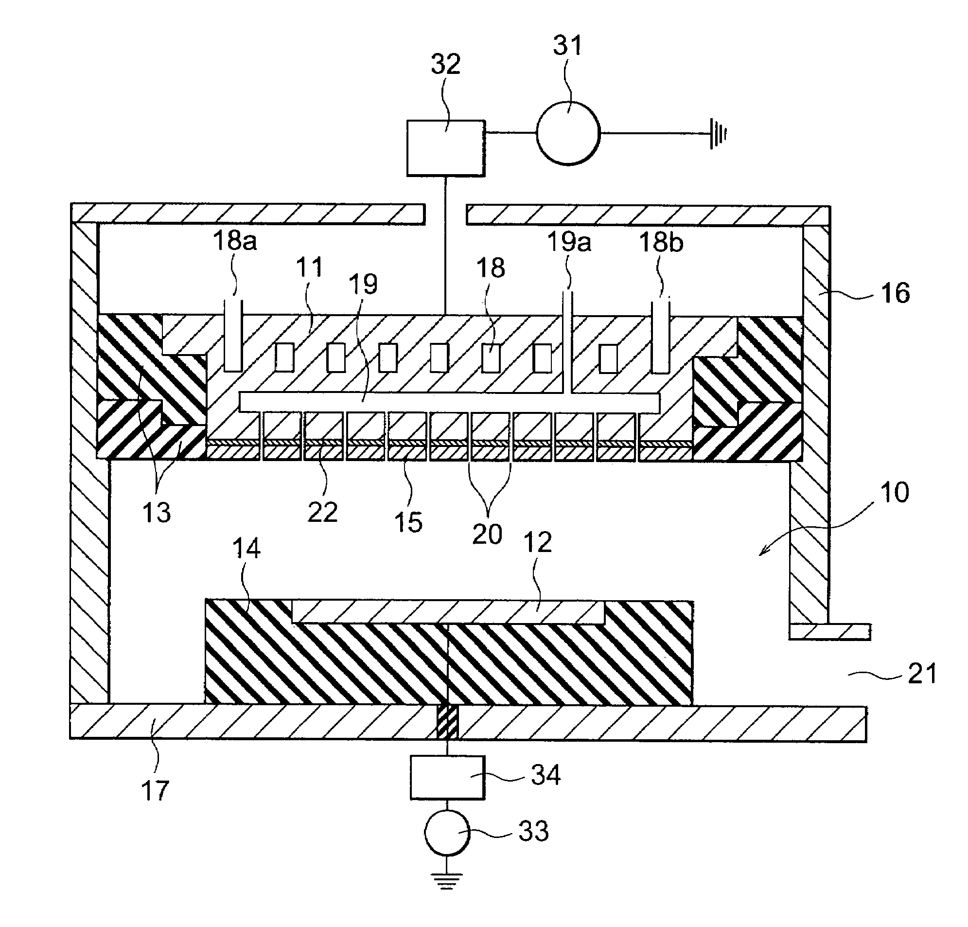
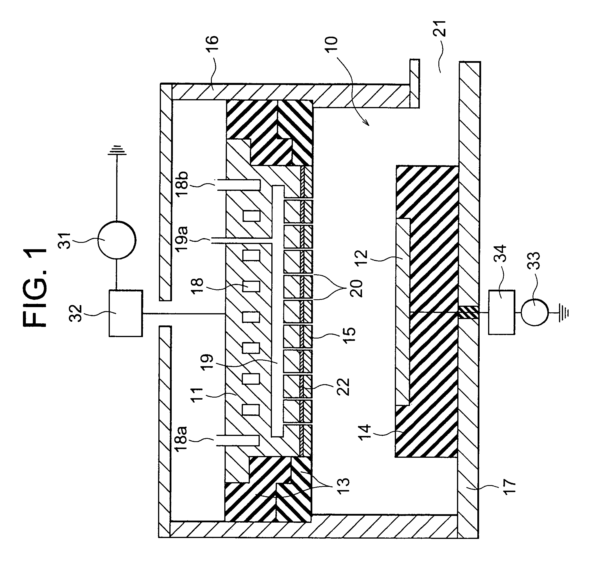
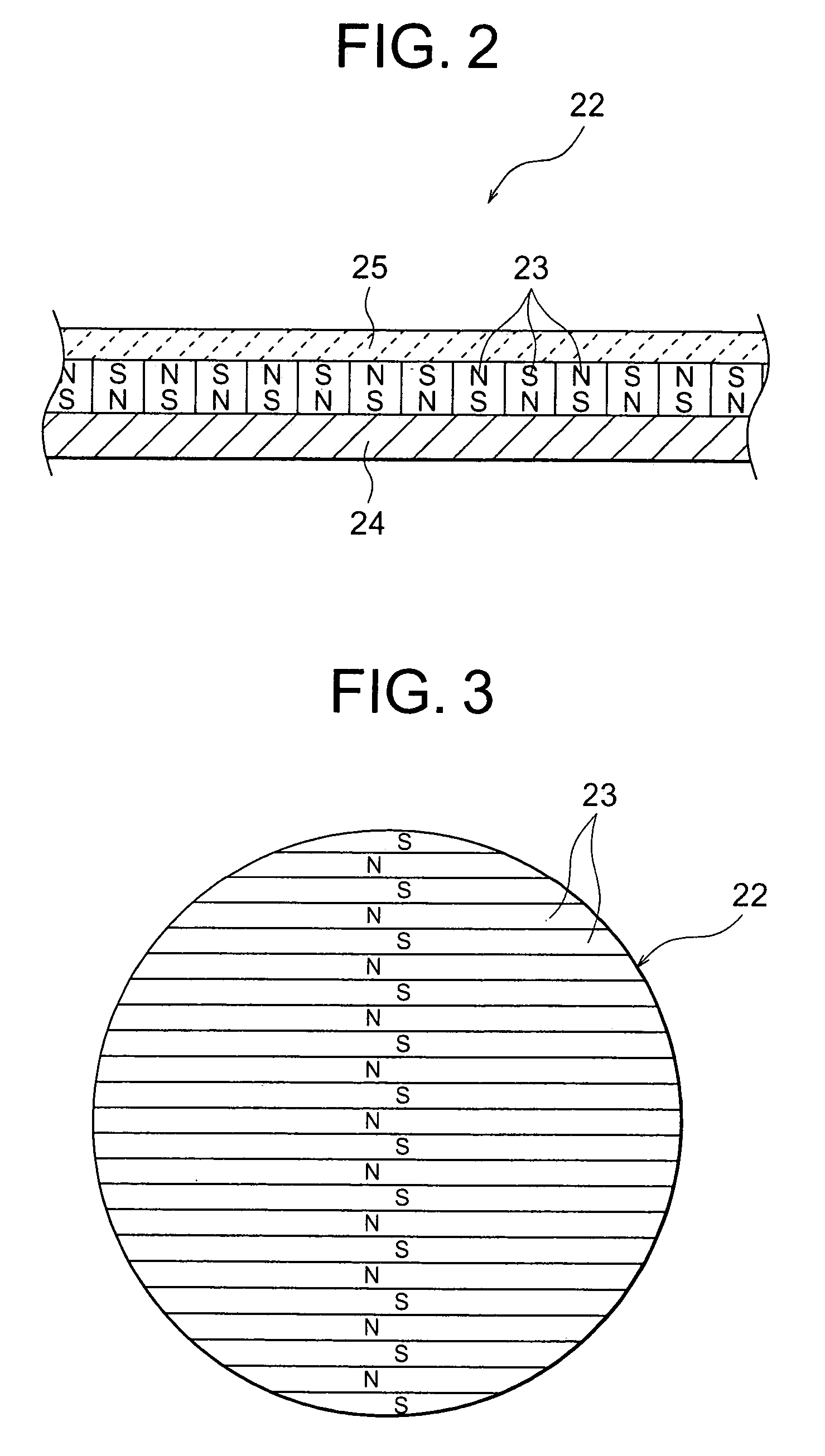
[0067]In accordance with the first embodiment, since the showerhead 15 is fixed or attached to whole area of the lower surface of the top electrode 11 by the magnetic force based on the sheet-like magnetic assembly 22, the temperature uniformity of the showerhead or the target and the gas distribution below the gas showerhead can be improved.

[0068]Next, the second embodiment of the present invention is explained by referring to FIG. 4. FIG. 4 shows an enlarged longitudinal cross sectional view of the section including the top electrode unit 11 and the showerhead 15. The second embodiment is an extension of the first embodiment. Therefore, in this second embodiment, only the characteristic section is shown and explained. The rest of the configuration is as same as those of the first embodiment.

[0069]The only difference between the first and second embodiments is the top electrode 11 is made of non-ferromagnetic metal such as aluminum (Al). Therefore, in order to attach the showerhead...

third embodiment

[0070]With reference to FIGS. 5 and 6, the present invention is explained. FIG. 5 shows an enlarged longitudinal cross sectional view of the top electrode 11 and the showerhead 15. FIG. 6 shows a bottom view of the magnet arrangement on the lower surface of the top electrode 11.

[0071]The third embodiment is a modification of the second embodiment. The top electrode 11 is also made of metal such as Al. On the lower surface of the top electrode 11, a plurality of separate magnets 42 is arranged such that magnetic poles of each of the neighboring magnets are selected to have alternate polarity. The magnets 42 are placed in holes formed on the lower surface and glued to the holes. The number of the magnets 42 is not critical and can be determined optionally depending to the area of the lower surface of the top electrode 11. The magnets 42 are usually placed with a separation of about a few centimeters, for example, 4 cm. The magnets 42 can be randomly placed within the lower surface of ...

fourth embodiment

[0077]As the modification of the fourth embodiment, one can use the showerhead 15 with only the thin ferromagnetic metal sheet 44. In this case, the magnets 43 and the deformable sheet 45 are not used. The showerhead 15 is then attached to the top electrode 11 only by the magnetic force generated by the magnets 42 within the top electrode 11.

[0078]The above fourth embodiment and its modification result in a lower temperature rise of the showerhead 15. All of the merits explained in the above first embodiment can be obtained by the fourth embodiment etc.

[0079]Next, the fifth embodiment of the present invention will be explained by referring to FIGS. 10, 11 and 12. FIG. 10 shows a longitudinal cross sectional view of the fifth embodiment of the present invention. The reactor 10 of this embodiment is a plasma-processing reactor. There is a plurality of magnets 51 placed in holes made within the top electrode 11.

[0080]The magnets 51 are arranged in a noncircular configuration with respe...


PUM

PropertyMeasurementUnit
thicknessaaaaaaaaaa
thicknessaaaaaaaaaa
thicknessaaaaaaaaaa

Abstract

A plasma processing system includes a reactor, a top electrode made of a magnetic or ferromagnetic metal or a metal-alloy, wherein a RF or DC power is applied to generate plasma within the reactor; a gas showerhead fixed to the top electrode; a sheet-like magnetic assembly bound to the upper surface of the gas showerhead, which includes a plurality of separate magnets, a metal sheet made of a ferromagnetic metal, and a deformable film.

Description

BACKGROUND OF THE INVENTION[0001]1. Field of the Invention[0002]The present invention relates to a device for fixing a gas showerhead or target to an RF or DC electrode in a plasma processing system. More particularly, the present invention relates to a technique to fix the gas showerhead used in plasma assisted chemical vapor depositions or dry etching systems, or the target used in plasma assisted sputter deposition systems to improve the thermal conductance from the showerhead or target to the RF or DC electrode and the gas distribution below the showerhead.[0003]2. Description of the Related Art[0004]Plasma assisted wafer processing technique is well-accepted method in semiconductor device manufacturing industry. Two major plasma generation techniques are the RF (Radio Frequency) plasmas and the DC (Direct Current) plasmas with parallel plate configuration, where RF or DC electrode is in parallel with a wafer surface. In most such plasma assisted wafer processing reactors there ...

Claims


Application Information

Patent Timeline
Patent Type & Authority Patents(United States)
IPC IPC(8): C23C16/455C23C14/34C23C16/00C23C16/503H05H1/46C23C14/35C23F4/00H01J37/32H01L21/205H01L21/304H01L21/3065
CPCH01J37/3244
Inventor WICKRAMANAYAKA, SUNILISHIHARA, MASAHITONOZAKI, YOSHIKAZUDOI, HIROSHI
Owner ANELVA CORP
Why Eureka
Try Eureka