Valve deactivation system and improved latchable HLA therefor

a deactivation system and latching technology, applied in the direction of valve arrangements, combustion engines, machines/engines, etc., can solve the problems of degradation in the condition of oil (i.e., cleanliness, chemical composition, etc., to have a negative impact on the operation of the unlatching system, and the amount of air in the oil

Active Publication Date: 2007-01-09
EATON INTELLIGENT POWER LTD
View PDF2 Cites 52 Cited by
  • Summary
  • Abstract
  • Description
  • Claims
  • Application Information

AI Technical Summary

Benefits of technology

[0010]It is a more specific object of the present invention to provide an improved valve control system in which a plurality of engine poppet valves may be deactivated utilizing only a single actuator.
[0011]It is another object of the present invention to provide an improved valve control system which accomplishes the above-stated objects, and in which the actuator used to achieve the transition between the activated and deactivated modes is not required to be an especially high performance type of actuator.
[0015]In accordance with another aspect of the present invention, an improved deactivating-type hydraulic lash compensation device is provided for use in a valve control system of an internal combustion engine including an engine poppet valve for controlling the flow to and from a combustion chamber. The lash compensation device comprises a body member adapted to be received within a bore defined by a housing, the body member being fixed relative to the housing. A plunger assembly is moveable relative to the body member, in a direction parallel to the axis of the device, and a latch member is moveable radially, relative to the axis, between a latched condition and an unlatched condition in which the plunger assembly is freely reciprocable relative to the body member. A spring member biases the latch member toward one of the latched and unlatched conditions.

Problems solved by technology

Although this known arrangement for achieving deactivation of an engine poppet valve has proven to be generally satisfactory in its limited commercial usage, there are certain inherent disadvantages in such a system.
In addition, any degradation in the condition of the oil (i.e., cleanliness, chemical composition, etc.) will have a negative impact on the operation of the unlatching system, as will the amount of air in the oil.

Method used


Image

  • Valve deactivation system and improved latchable HLA therefor
  • Valve deactivation system and improved latchable HLA therefor
  • Valve deactivation system and improved latchable HLA therefor

Examples


Embodiment Construction

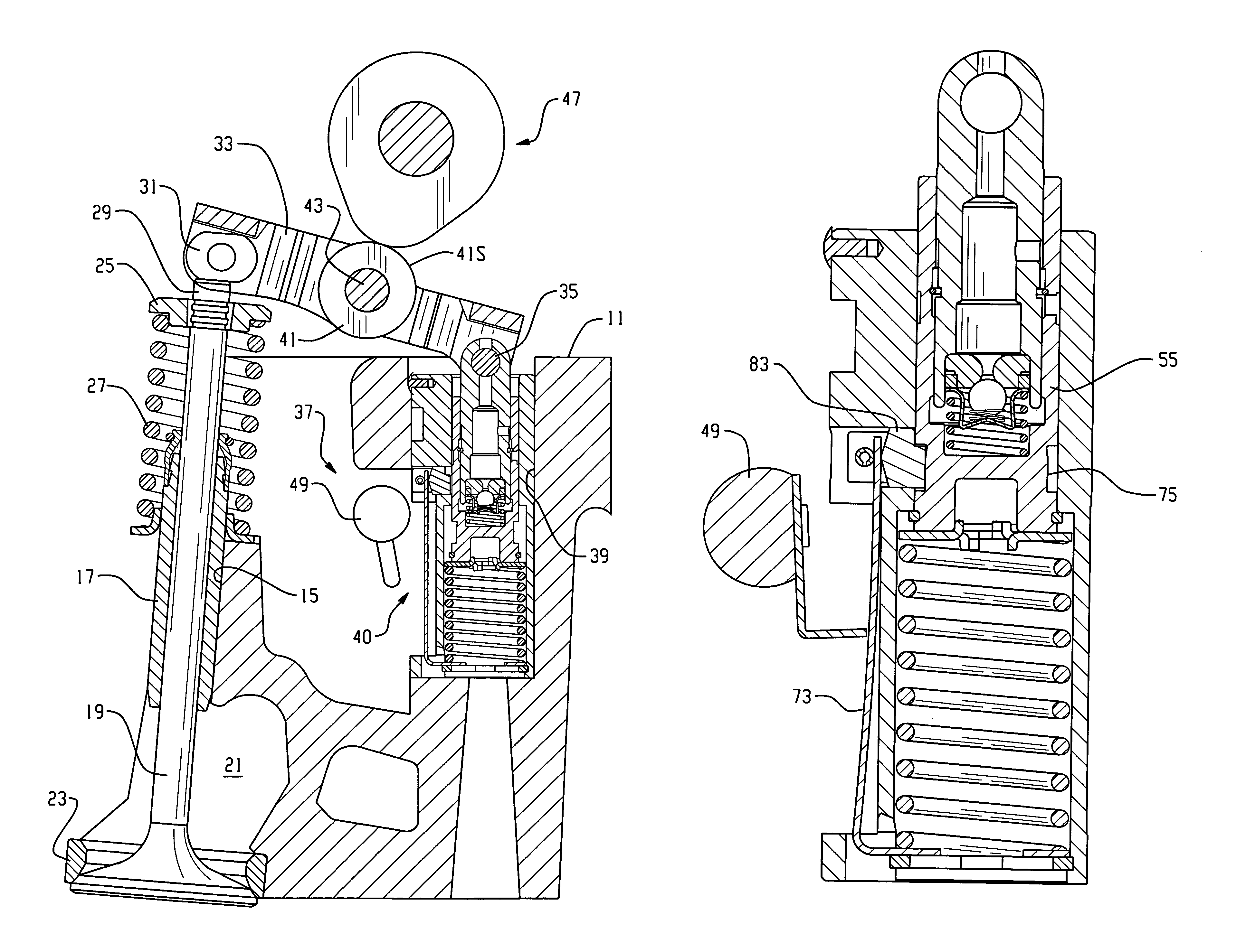
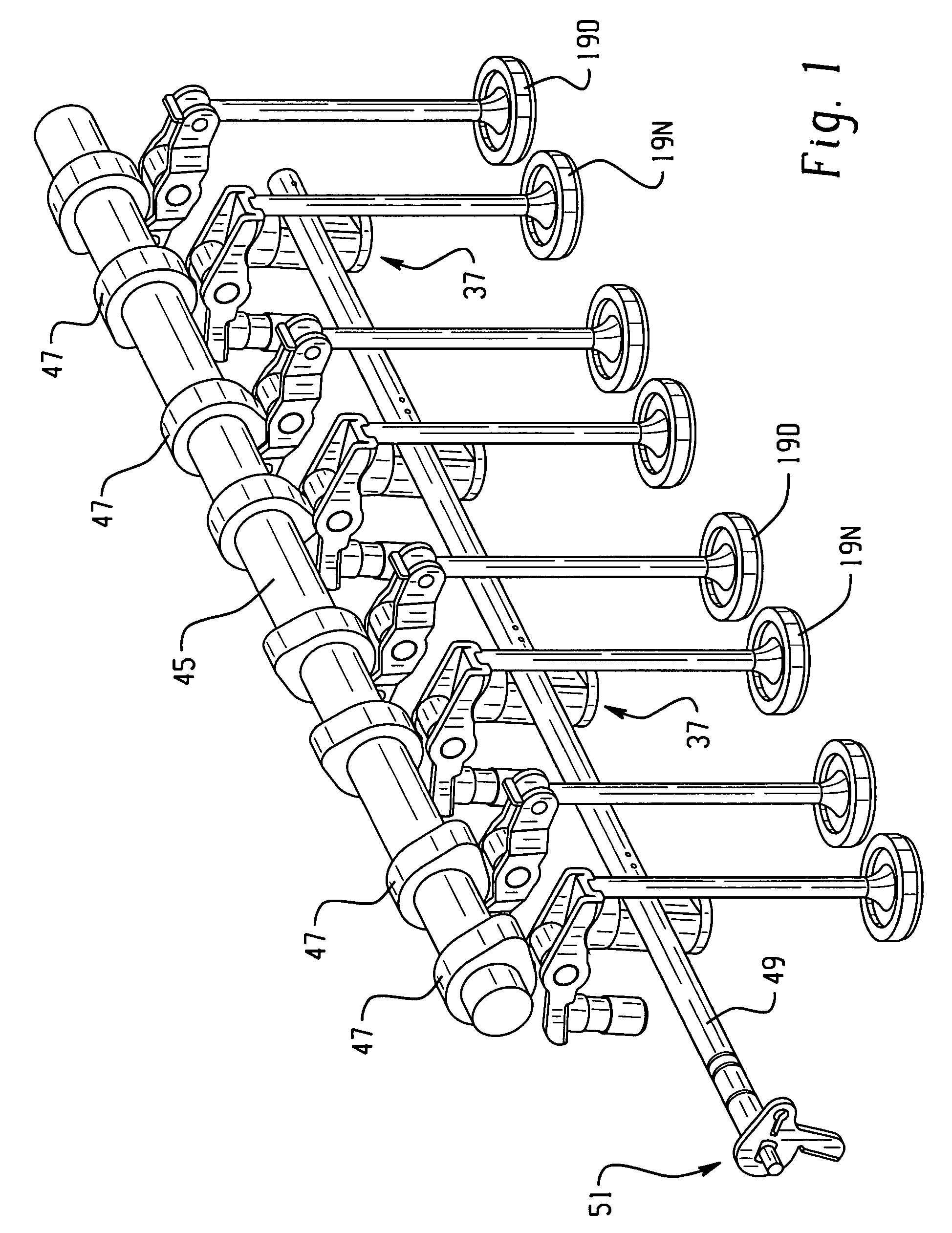
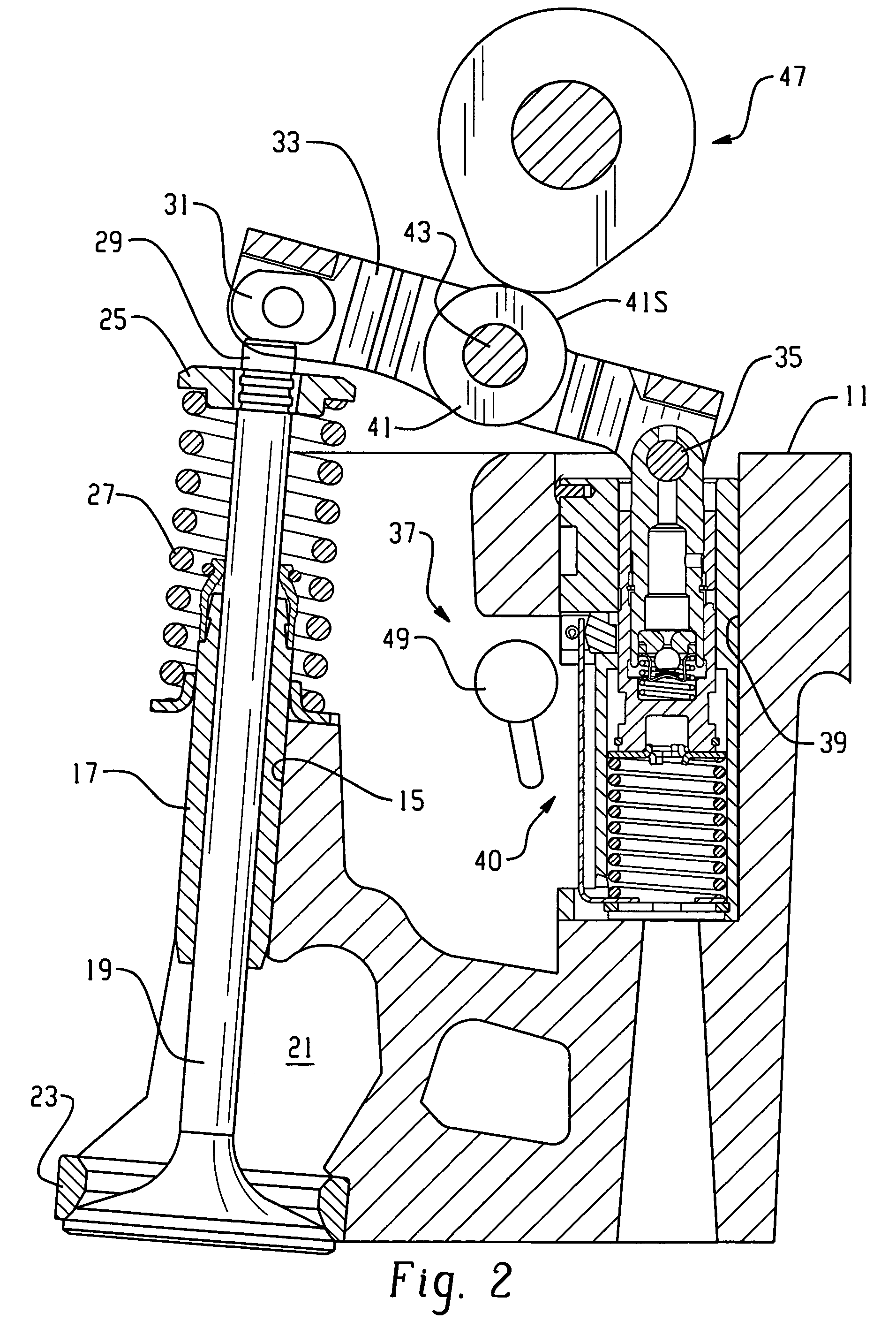
[0023]Referring now to the drawings, which are not intended to limit the invention, FIGS. 1 and 2 taken together illustrate a valve actuation system made in accordance with the present invention. It should be noted that whereas FIG. 2 illustrates a cylinder head, generally designated 11, the cylinder head 11 is not shown in FIG. 1, in order to facilitate viewing all of the key components of the valve drive and control system of the present invention.

[0024]Referring now primarily to FIG. 2, as is well known to those skilled in the art, the cylinder head 11 typically defines the upper extent of a combustion chamber, designated 13 in FIG. 2. The cylinder head 11 defines a plurality of slightly angled bores 15, and disposed within each bore 15 is a valve guide 17 which supports, for reciprocable movement therein, an engine poppet valve 19. In the subject embodiment, and by way of example only, the valve control system is utilized to control only intake poppet valves, and therefore, as w...


PUM


Abstract

A deactivating valve control system for an internal combustion engine and, for each deactivating intake poppet valve (19D), there is provided a deactivating lash compensation device (37). Each of the devices (37) includes a latch member (83) biased toward an unlatched condition (FIG. 3) by a spring member 69, including a vertically-extending spring portion (73). In one embodiment (FIG. 1), the deactivation system includes an actuation rod (49) which is rotated to overcome the biasing force of the spring members (69) and move the latch members (83) into latching engagement (FIG. 5). In another embodiment (FIG. 7), an actuation wire (105) is reciprocated linearly to pivot a lever member (99) associated with each deactivating device (37), again to overcome the spring (69) and move the latch member (83) into latching engagement.

Description

BACKGROUND OF THE DISCLOSURE[0001]The present invention relates to a valve control system for an internal combustion engine, and more particularly, to such a system of the type which can be used to deactivate the engine poppet valves of a number of different cylinders. The present invention also relates to an improved deactivating-type hydraulic lash adjuster (HLA) for use in such a valve control system.[0002]Variable valve control systems of the valve deactivation type for engine poppet valves are already generally well known in the art. Although such valve deactivation type valve control systems can be applied to either the intake poppet valve, or the exhaust poppet valve, or both, it is most common to utilize such a valve deactivation system to select between the activated and de-activated conditions of only the intake poppet valves, and the invention will be described in connection with such a system.[0003]Valve control systems of the type including “valve deactivation” capabili...

Claims


Application Information

Patent Timeline
Patent Type & Authority Patents(United States)
IPC IPC(8): F01L1/18F01L1/24F01L13/00F02D13/06
CPCF01L1/18F01L1/2405F02D13/06F01L13/0005Y02T10/18Y02T10/12
Inventor CECUR, MAJOCONTARIN, FABIANO
Owner EATON INTELLIGENT POWER LTD
Why Eureka
Try Eureka