Plasma display unit

a technology of plasma and display unit, which is applied in the manufacture of electric discharge tubes/lamps, discharge tubes luminescnet screens, and electrodes, etc., can solve the problems of disadvantageous clogging of nozzles, increased surface area of particles, and increased chromaticity of phosphor, so as to reduce luminance degradation and chromaticity change of phosphor, and improve the discharge characteristic of phosphor. , the effect of reducing water adsorption

Inactive Publication Date: 2007-01-09
PANASONIC CORP
View PDF7 Cites 14 Cited by
  • Summary
  • Abstract
  • Description
  • Claims
  • Application Information

AI Technical Summary

Benefits of technology

[0010]The present invention addresses the problems discussed above, and aims to suppress of adsorption of water and carbon hydride onto a surface of a blue phosphor, reduce luminance degradation and chromaticity change of the phosphor, and improve a discharge characteristic of the phosphor, by eliminating occurrence of oxygen defects existing near Ca, Sr, Ba, or Eu ions in the blue phosphor.

Problems solved by technology

When the grain size of the phosphor particles is decreased, however, the surface area of the particles increases and a defect in the phosphor is apt to increase.
When the ethylcellulose and the blue phosphor are separated from each other, the blue phosphor is apt to accumulate near a nozzle opening having zero velocity gradient especially in the inkjet method, and hence the nozzle is disadvantageously clogged.
The coating of the entire surface newly causes absorbing of ultraviolet rays to decrease light emitting luminance of the phosphor, and the coating cannot sufficiently prevent the decrease of luminance due to the ultraviolet rays.
The phosphor used in a PDP or the like is manufactured by a solid-phase reaction method or an aqueous solution reaction method, but decreasing of the grain size is apt to generate a defect.
In the solid-phase reaction method, especially, sintering or crushing the phosphor in reducing atmosphere is known to generate many defects.
The generation of these defects is considered to cause luminance degradation of the conventional blue phosphor by itself.
In other words, it has been considered that a defect generated by an impact on the phosphor from an ion occurring in driving the panel or a defect generated by the ultraviolet rays having 147 nm of wavelength causes the luminance degradation.

Method used


Image

  • Plasma display unit
  • Plasma display unit
  • Plasma display unit

Examples


exemplary embodiment 1

(Exemplary Embodiment 1)

[0046]A plasma display device in accordance with an exemplary embodiment of the present invention will be described with reference to drawings.

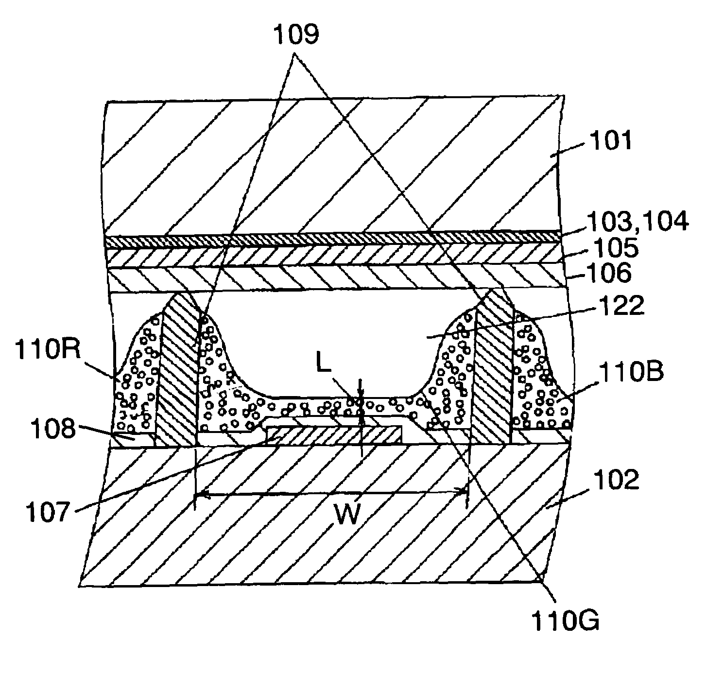
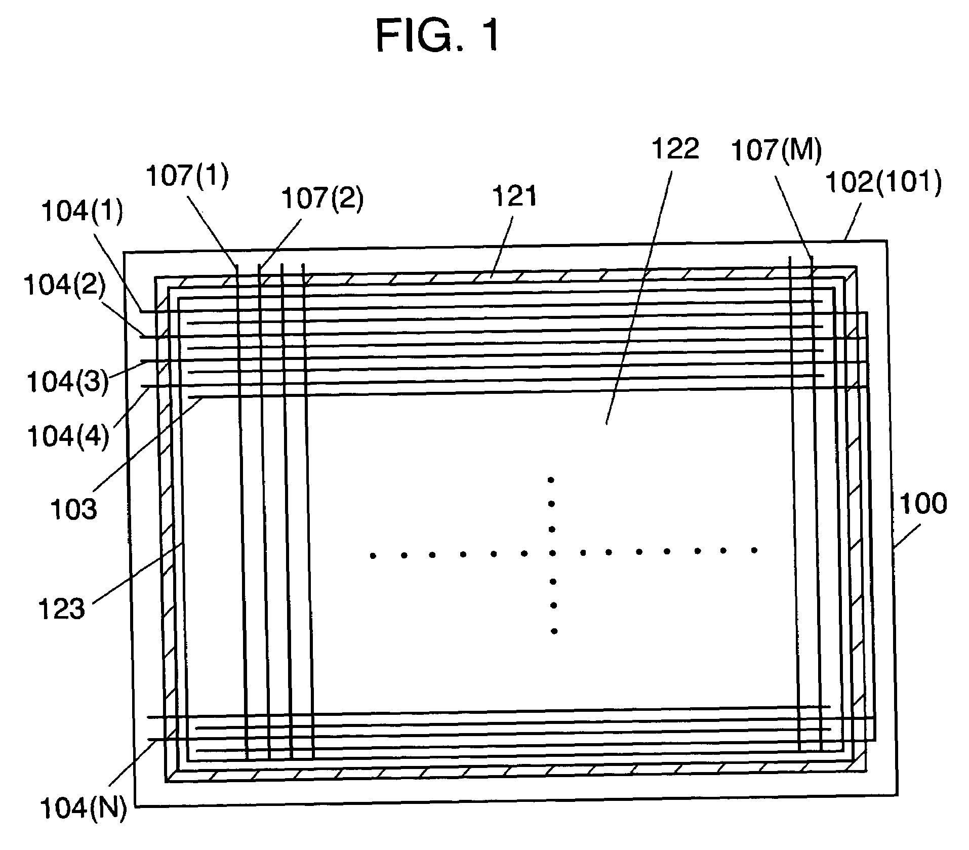
[0047]FIG. 1 is a schematic diagram of the PDP in a removed state of a front glass substrate. FIG. 2 is a partially sectioned perspective view of an image display region of the PDP. In FIG. 1, the respective numbers of display electrodes, display scan electrodes, and address electrodes are reduced for the sake of clarity.

[0048]In FIG 1, PDP 100 includes front glass substrate 101, back glass substrate 102, N display electrodes 103, N display scan electrodes 104 (1) to 104 (N)), M address electrodes 107 (107 (1) to 107 (M)), and airtight seal layer 121. The inner region of airtight seal layer 121 is image display region 123. The PDP of the exemplary embodiment has an electrode matrix having three-electrode structure formed of display electrodes 103, display scan electrodes 104, and address electrodes 107. Discharge cells...


PUM

PropertyMeasurementUnit
temperatureaaaaaaaaaa
grain sizeaaaaaaaaaa

Abstract

A plasma display device includes a blue phosphor composed of a compound represented by Me3MgSi2O8:Eu (where, Me is at least calcium (Ca), strontium (Sr), or barium (Ba)). Concentration of bivalent Eu ions is 45 to 95% and concentration of trivalent Eu ions is 5 to 55%, of the europium (Eu) atoms contained in the blue phosphor layer. The plasma display device has less luminance degradation in a panel manufacturing process, high luminance, and long lifetime.

Description

TECHNICAL FIELD[0001]The present invention relates to a plasma display device that is used for image display on a television or the like and has a phosphor layer excited by ultraviolet rays to emit light, and related to a phosphor thereof.BACKGROUND ART[0002]Recently, in the field of a color display device used for image display on a computer or a television, a plasma display device including a plasma display panel (PDP) receives attention because it can be enlarged, thinned, and lightened. The plasma display device displays an image in full color by additive mixing of so-called three primary colors (red, green, blue). For performing the full color display, the plasma display device has a phosphor layer for emitting light of each of three primary colors, red (R), green (G), and blue (B), and phosphor particles constituting the phosphor layer are excited by ultraviolet rays generated in a discharge cell of the PDP and hence generate visible light of each color.[0003]A compound is use...

Claims


Application Information

Patent Timeline
Patent Type & Authority Patents(United States)
IPC IPC(8): C01B25/00C01B25/01C01B25/02H01J1/14C09K11/59C09K11/08C09K11/77H01J11/12H01J11/22H01J11/24H01J11/26H01J11/34H01J11/42
CPCC09K11/7734H01J2211/42C09K11/77342H01J11/42
Inventor KAWAMURA, HIROYUKISUGIMOTO, KAZUHIKOAOKI, MASAKIOTANI, MITSUHIROSETOGUCHI, HIROSHIHIBINO, JUNICHI
Owner PANASONIC CORP
Why Eureka
Try Eureka