Array of micromirror array lenses

a micromirror array and array technology, applied in the direction of mirrors, instruments, mountings, etc., can solve the problems of complex driving mechanisms to control the relative positions of refractive lenses, slow response time, and slow response time typically on the order of hundreds of milliseconds, and achieve small focal length variation and low focusing efficiency.

Active Publication Date: 2007-01-09
STEREO DISPLAY
View PDF22 Cites 68 Cited by
  • Summary
  • Abstract
  • Description
  • Claims
  • Application Information

AI Technical Summary

Benefits of technology

[0011]The micromirror array lens can be formed by a polar array of the micromirrors. For the polar array, each micromirror has a fan shape to increase an effective reflective area, so that the optical efficiency increases. The aberration of the micromirror array lens can be reduced by micromirrors with curvatures. The optical efficiency of the micromirror array lens can be improved by locating a mechanical structure upholding micromirrors and the actuating components under micromirrors to increase an effective reflective area. Electric circuits to operate the micromirrors can be replaced with known microelectronics such as MOS or CMOS. Applying the microelectronics circuits under micromirror array, the effective reflective area can be increased by removing necessary area for electrode pads and wires. The lens can correct aberration, which is caused by optical effects due to the medium between the object and its image or is caused by defects of a lens system that cause its image to deviate from the rules of paraxial imagery, by controlling each micromirror independently. Independent control of each micromirror is also possible by replacing electric circuits required for control with known microelectronics technologies and fabricating the ciruits underneath the micromirrors using known microfabrication methods.
[0029]The lens is an adaptive optical component. Therefore the lens compensates for phase errors of light due to the medium between an object and its image; corrects aberrations; corrects the defects of an imaging system that cause the image to deviate from the rules of paraxial imagery. Also an object which does not lie on the optical axis can be imaged by the lens without macroscopic mechanical movement.

Problems solved by technology

It has complex driving mechanisms to control the relative positions of refractive lenses and a slow response time.
Unfortunately, it has a slow response time typically on the order of hundreds of milliseconds.
Even though the fastest response liquid crystal lens has the response time of tens of milliseconds, it has small focal length variation and low focusing efficiency.

Method used


Image

  • Array of micromirror array lenses
  • Array of micromirror array lenses
  • Array of micromirror array lenses

Examples


Embodiment Construction

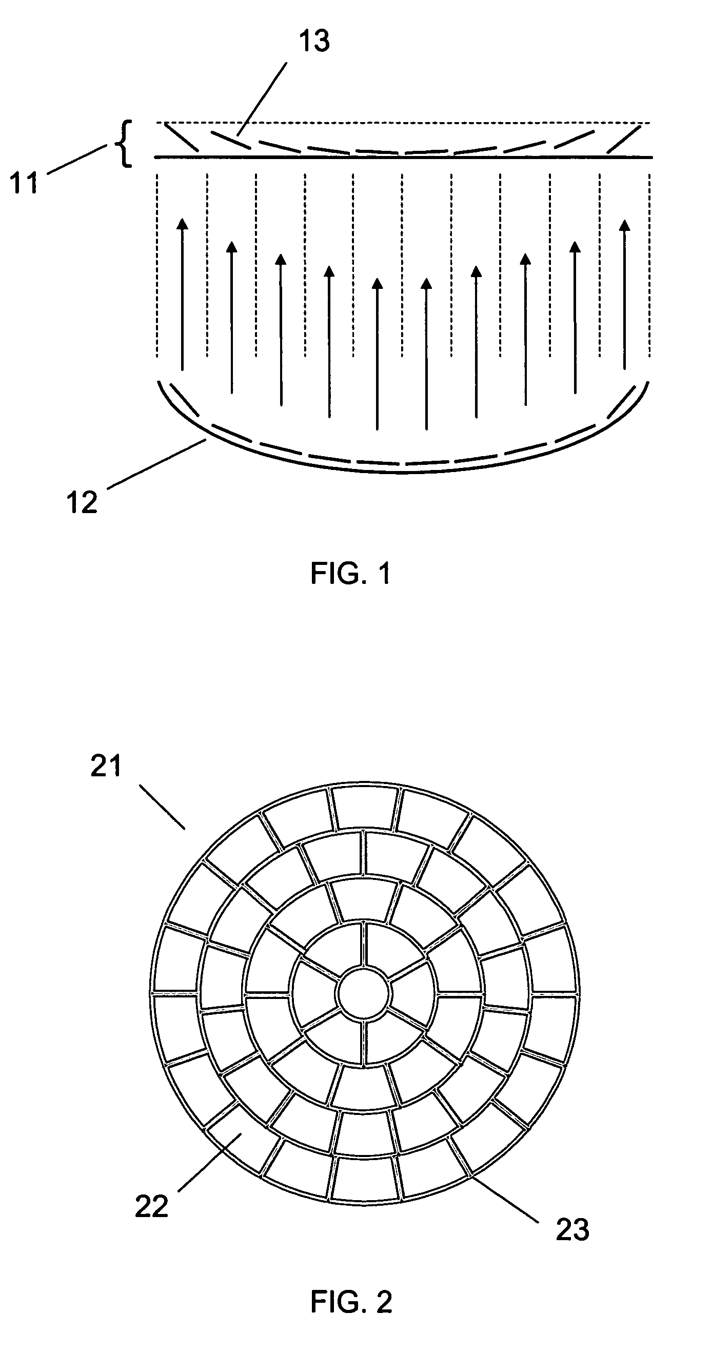
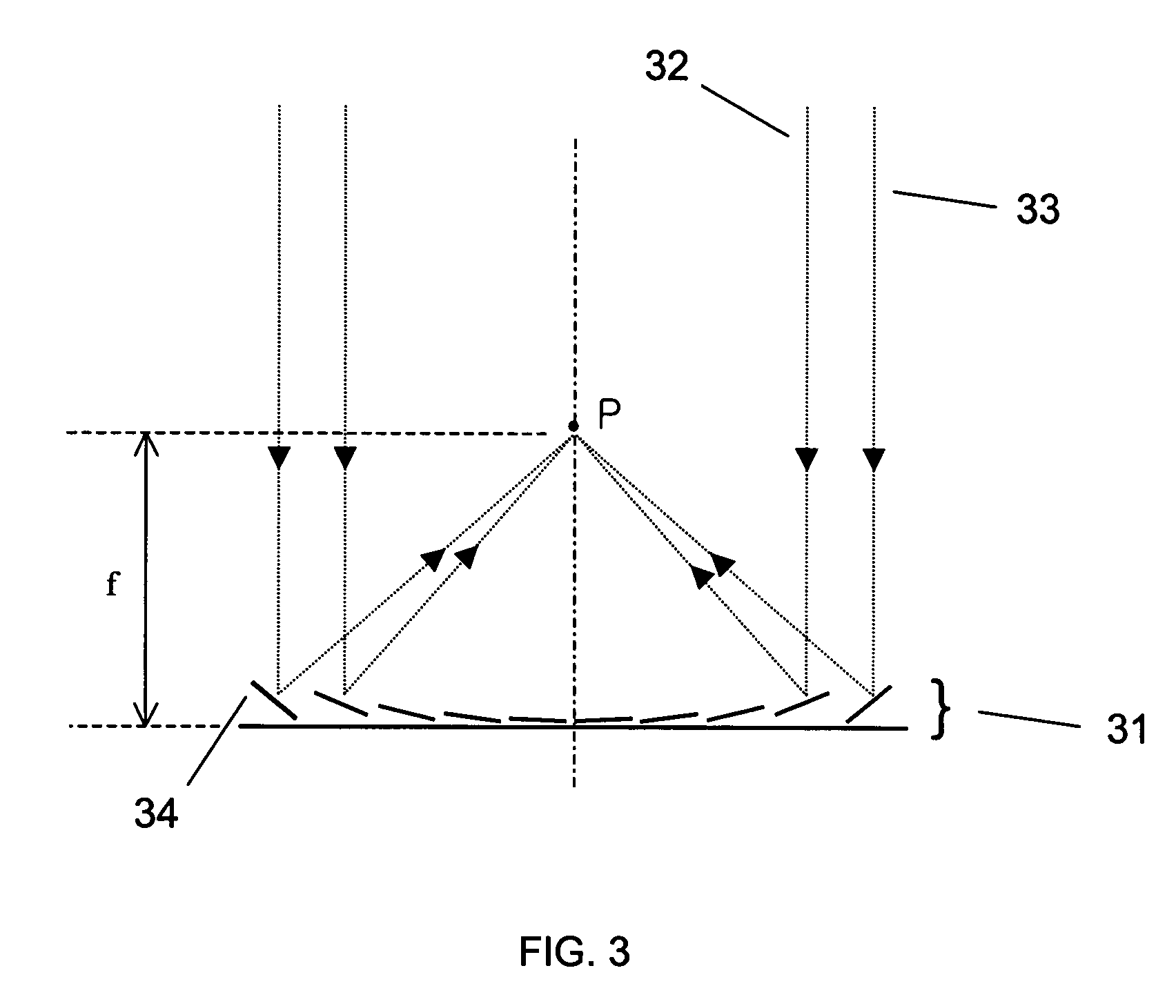
[0047]FIG. 1 illustrates the principle of the micromirror array lens 11. There are two conditions to make a perfect lens. The first is the converging condition that all light scattered by one point of an object should converge into one point of the image plane. The second is the same phase condition that all converging light should have the same phase at the image plane. To satisfy the perfect lens conditions, the surface shape of conventional reflective lens 12 is formed to have all light scattered by one point of an objective to be converged into one point of the image plane and have the optical path length of all converging light to be same.

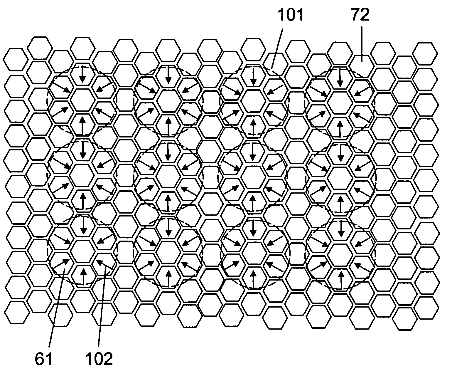
[0048]A micromirror array arranged in flat plane can satisfy two conditions to be a lens. Each of the micromirrors 13 rotates to converge the scattered light. Because all micromirrors 13 of the micromirror array lens 11 are arranged in a flat plane as shown in FIG. 1, the optical path length of lights converged by rotation of the micromirrors ...


PUM


Abstract

An array of micromirror array lenses is invented. The micromirror array lens consists of many micromirrors and actuating components. Each micromirror array lens is variable focal length lens with high speed focal length change. The lens can have arbitrary type and / or size as desired and desired arbitrary optical axis and can correct aberration by controlling each micromirror independently. Independent control of each micromirror is possible by known microelectronics technologies. The actuating components control the positions of micromirrors electrostatically and / or electromagnetically. The optical efficiency of the micromirror array lens is increased by locating a mechanical structure upholding micromirrors and the actuating components under micromirrors. The known microelectronics technologies remove the loss in effective reflective area due to electrode pads and wires.

Description

BACKGROUND OF THE INVENTION[0001]The present invention relates to an array of micromirror array lenses and operational methods for the lens.[0002]A most widely used conventional variable focal length system is the one using two refractive lenses. It has complex driving mechanisms to control the relative positions of refractive lenses and a slow response time. Alternatively, variable focal length lenses have been made. Variable focal length lenses can be made by changing the shape of the lens, as is found in the human eye; this method has been used in lenses made with isotropic liquids. Other lenses have been made of electrically variable refractive index media to create either a conventional lens or a gradient index lens by means of a voltage gradient. The electrically variable refractive index allows the focal length of the lenses to be voltage controlled. Among them, the most advanced variable focal length lens is a liquid crystal variable focal length lens, which has a complex me...

Claims


Application Information

Patent Timeline
Patent Type & Authority Patents(United States)
IPC IPC(8): G02B26/00G02B26/08G02B5/08G02B5/10G02B7/182G02B27/10
CPCG02B26/0833
Inventor KIM, TAE HYEONBAEK, SANG HYUNE
Owner STEREO DISPLAY
Why Eureka
Try Eureka