Robot-based automation system for cryogenic crystal sample mounting

a robotic and crystal technology, applied in the field of robotic and crystal crystal mounting and alignment, can solve the problems of limiting the collection step of high throughput x-ray data collection, the current capability of instruments at third generation synchrotron beamlines, and increasing the number of samples to be investigated, so as to achieve the effect of maximizing the dewar space usage and near-micron positioning repeatability

Inactive Publication Date: 2007-01-16
UCHICAGO ARGONNE LLC +1
View PDF11 Cites 17 Cited by
  • Summary
  • Abstract
  • Description
  • Claims
  • Application Information

AI Technical Summary

Benefits of technology

[0014]In accordance with features of the invention, a miniature liquid nitrogen reservoir with a check valve is mounted on one of the fingers of the robot handset close to the fingertip. During the initial cooling process the handset is open and the miniature reservoir is submerged in the liquid nitrogen storage Dewar. A check valve ball is unseated allowing air to exit and liquid nitrogen to fill the reservoir through a jet hole and the check valve. In the crystal retrieval orientation, the check valve is closed, preventing loss of the liquid nitrogen and leaving the jet hole as the only opening. During the robot movement for retrieval, gradual warming of the fingers has vaporized liquid nitrogen from the reservoir resulting in a dry

Problems solved by technology

A limiting step in the collection of high throughput x-ray data collection is the mounting and alignment of individual protein crystals in the X-ray beam which is normally done by hand.
One of limitations in reaching the target goals of structural genomics is the current capability of instrumentation at third generation synchrotron beamlines.
Furthermore, added constraints increase the number of samples to be investigated.
In addition, crystals are fragile and show significant variations in quality, therefore several cr

Method used


Image

  • Robot-based automation system for cryogenic crystal sample mounting
  • Robot-based automation system for cryogenic crystal sample mounting
  • Robot-based automation system for cryogenic crystal sample mounting

Examples


Embodiment Construction

[0023]In accordance with features of the invention, a robotic system is provided that can efficiently and effectively carry out this process, without human intervention and which can hold a total, for example, of 120 different crystal samples at the correct cryogenic temperature. This invention should dramatically increase the rate at which protein structures can be determined experimentally.

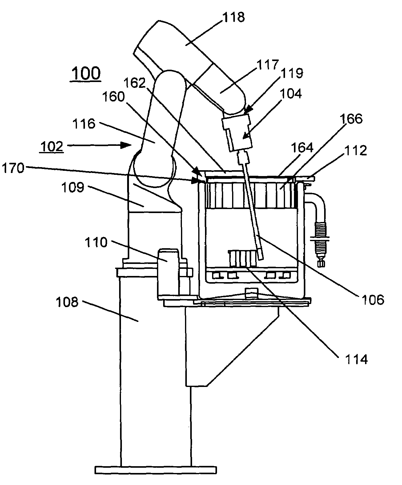
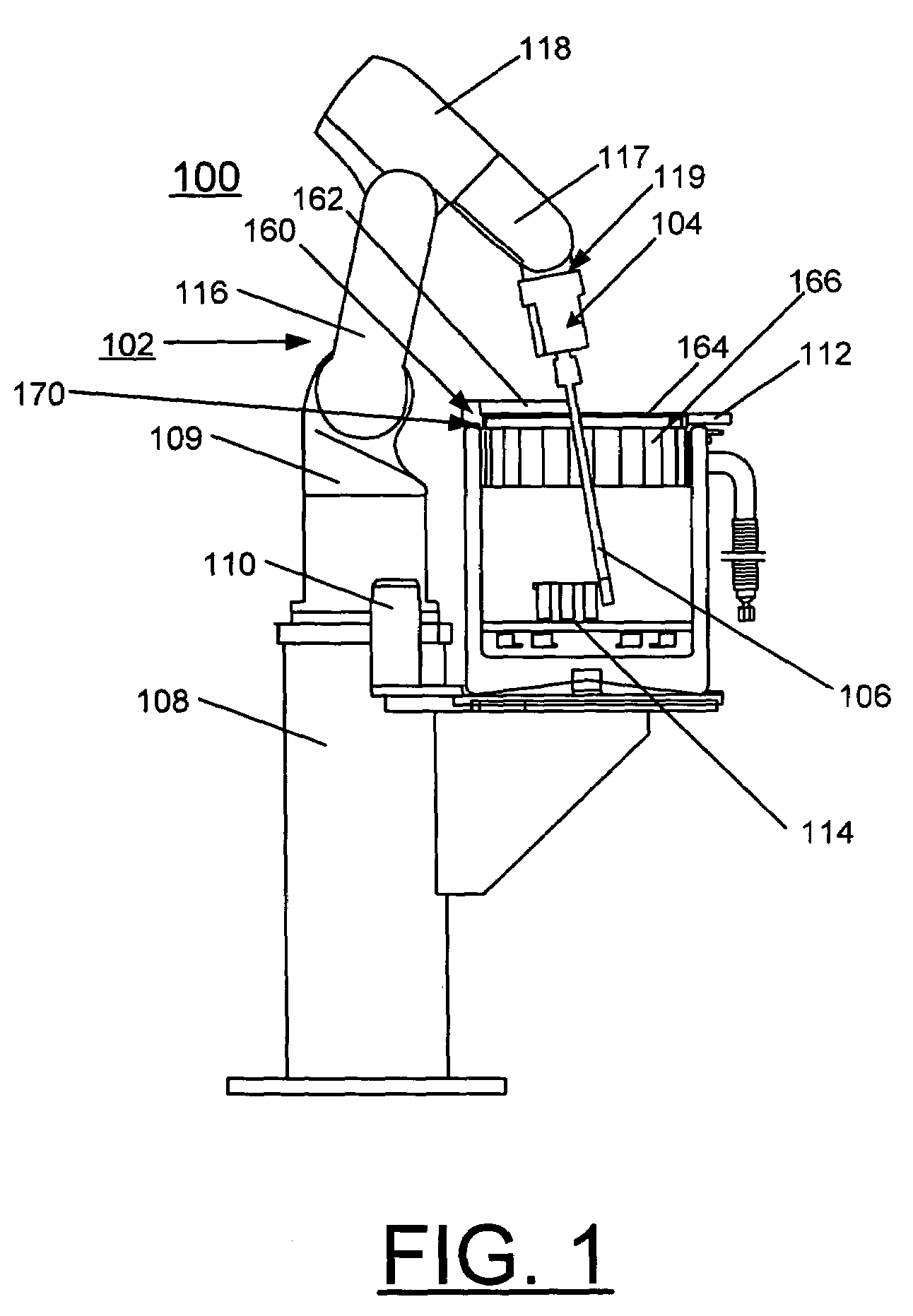
[0024]Having reference now to the drawings, FIG. 1 shows the side-view and top-view of the robot-based automation system for cryogenic crystal sample mounting generally designated by reference character 100 in accordance with the preferred embodiment. System 100 includes an industrial robot arm generally designated by reference character 102.

[0025]In accordance with features of the invention, system 100 provides an industrial robot-based automation system for cryogenic crystal sample mounting. With this system 100, for example up to 120 of crystal samples, in eight magazines, each containing 15 ...


PUM


Abstract

A method and robot-based automation system are provided for cryogenic crystal sample mounting, for example, for use for cryogenic crystal sample mounting in the x-ray crystallography station at an x-ray source. The system includes a robot arm carrying a handset. The handset includes a pair of elongated fingers for sample mounting, and each finger carrying a set of strain gauge arrays for providing force sensing. A slim finger design allows a sample mounting process with no interference with the beam stop, cryostreem and x-ray detectors. The handset can detect the contact force intensity and direction; provide a precise gripping action; and feel the results of the gripping. The finger design incorporates a mechanism to maintain the sample temperature well below the cryogenic safety margin for the crystal viability. A Dewar container is provided with an ice control system and liquid nitrogen flow control. A triangular sample magazine maximizes the Dewar space usage. A miniature kinematical mounting sample holder provides near micron positioning repeatability. These capabilities make the robot-arm more powerful, flexible, and reliable.

Description

[0001]This application claims the benefit of U.S. Provisional Application No. 60 / 459,101, filed on Mar. 31, 2003.CONTRACTUAL ORIGIN OF THE INVENTION[0002]The United States Government has rights in this invention pursuant to Contract No. W-31-109-ENG-38 between the United States Government and Argonne National Laboratory.FIELD OF THE INVENTION[0003]The present invention relates to a method and robot-based automation system for the mounting and alignment of crystals to be examined in an x-ray beam. The complete process is carried out at extremely low temperatures in order to minimize potential damage to the crystals.DESCRIPTION OF THE RELATED ART[0004]X-ray crystallography is an important method by which the three dimensional structure or shape of molecules can be determined. One of the most important class of molecules examined are proteins and with the recent completion of the human genome, biologists are now seeking new ways to solve protein structures in a high-throughput mode. Al...

Claims


Application Information

Patent Timeline
IPC IPC(8): F25D25/00F25B19/00H05G1/00B25J11/00
CPCB25J11/00
Inventor SHU, DEMINGJOACHIMIAK, ANDRZEJPREISSNER, CURT A.NOCHER, DANIELHAN, YUFENGBARRAZA, JR., JUANLEE, PETERLEE, WAH-KEATCAI, ZHONGHOUGINELL, STEPHANALKIRE, RANDYSCHUESSLER, ROBERT G.
Owner UCHICAGO ARGONNE LLC
Why Eureka
Try Eureka