Reactor assembly and processing method

Inactive Publication Date: 2007-01-16
LAM RES CORP
View PDF25 Cites 32 Cited by
  • Summary
  • Abstract
  • Description
  • Claims
  • Application Information

AI Technical Summary

Benefits of technology

[0009]An inlet manifold assembly suitable for use in the reactor assembly comprises an inlet end portion comprising a cylindrically shaped conduit; and a flow-shaping portion comprising a first end opening in fluid communication with the inlet end port

Problems solved by technology

Axial flow reactor assemblies often fail to provide a uniform distribution of gas and / or reactive gaseous species across the substrate resulting in variations in the shape and size of the etched features, the thickness of the deposited layer, or the like.
This can lead to flow anomalies and non-uniformity in exposure of the gas and / or reactant to the substrate surface as effluent from the process on the substrate surface combines with the incoming gas flow.
Gas distribution systems typically include the use of specialized plates that are difficult to predict analytically and are largely designed by trial and error experimental methods.
However, one problem with the use of baffle plates and / or gas distribution plates disposed upstream from the substrate is the potential for reactive species recombination.
The recombination of reactive species can decrease the overall efficiency of the process, thereby increasing process times and reducing throughput.
The use of these materials adds to the overall costs and complexity of the reactor assembly.
The heating of the baffle plate can cause loss of substrate temperature control within the process chamber as each subsequent substrate is now heated by the energy contained within the baffle plate and not by the chamber heating device, i.e., lamp array, heated chuck, or the like.
In addition, the increased volume increases gas residence time that can be counterproductive in a process that is not reaction rate limited, e.g., a bulk photoresist stripping process, resulting in increased processing times.
However, process chambers having ceramic walls or ceramic ceilings are difficult to fabricate with nozzle feedthroughs extending therethrough.
Ceramic walls of polycrystalline ceramic material, such as aluminum oxide or silicon, are brittle materials and it is difficult to machine feedthrough holes in these materials without breaking or otherwise damaging the ceramic.
Also, other components, such as RF induction coils, which are typically located adjacent to the ceramic walls further reduce the available space for locating a gas nozzle through the ceramic walls without increasing the overall size (height) of the reactor assembly.
An axisymmetrically positioned exhaust conduit can result in asymmetric flow rates of gas across the substrate surface causing non-uniformity.
Furthermore, as substrates increase in diameter to 300 mm and beyond, the corresponding increases in the volume of the process chamber and surface area of the substrate makes it even more difficult to provide a uniform distribution of process gas across the entire surface of the substrate.
Another problem arises when a portion of the gas distributor is made from metal and is located within the energized plasma sheath in the process chamber.
In addition, the plasma species often chemically erode the metal to form contaminant particles that deposit upon the substrate.
Thus, it is generally required for the metal portions of the gas distributor to be protected from erosion by adding a ceramic coating to the metal surface, thereby adding to the expense and complexity of the reactor assembly.
This method of gas distribution can add considerable cost to the reactor in both materials and engineering time required to solve these problems.

Method used


Image

  • Reactor assembly and processing method
  • Reactor assembly and processing method
  • Reactor assembly and processing method

Examples


example 1

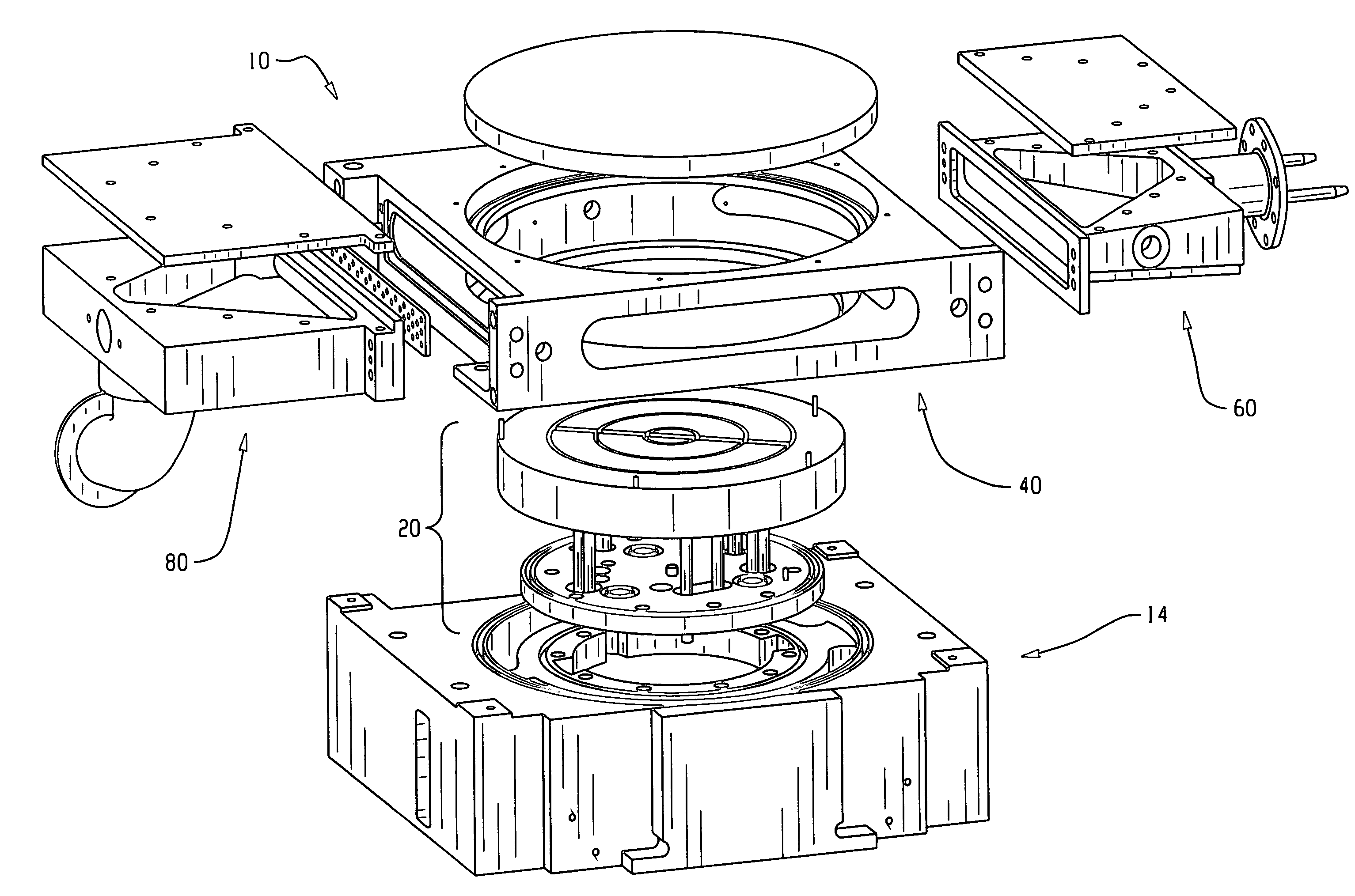
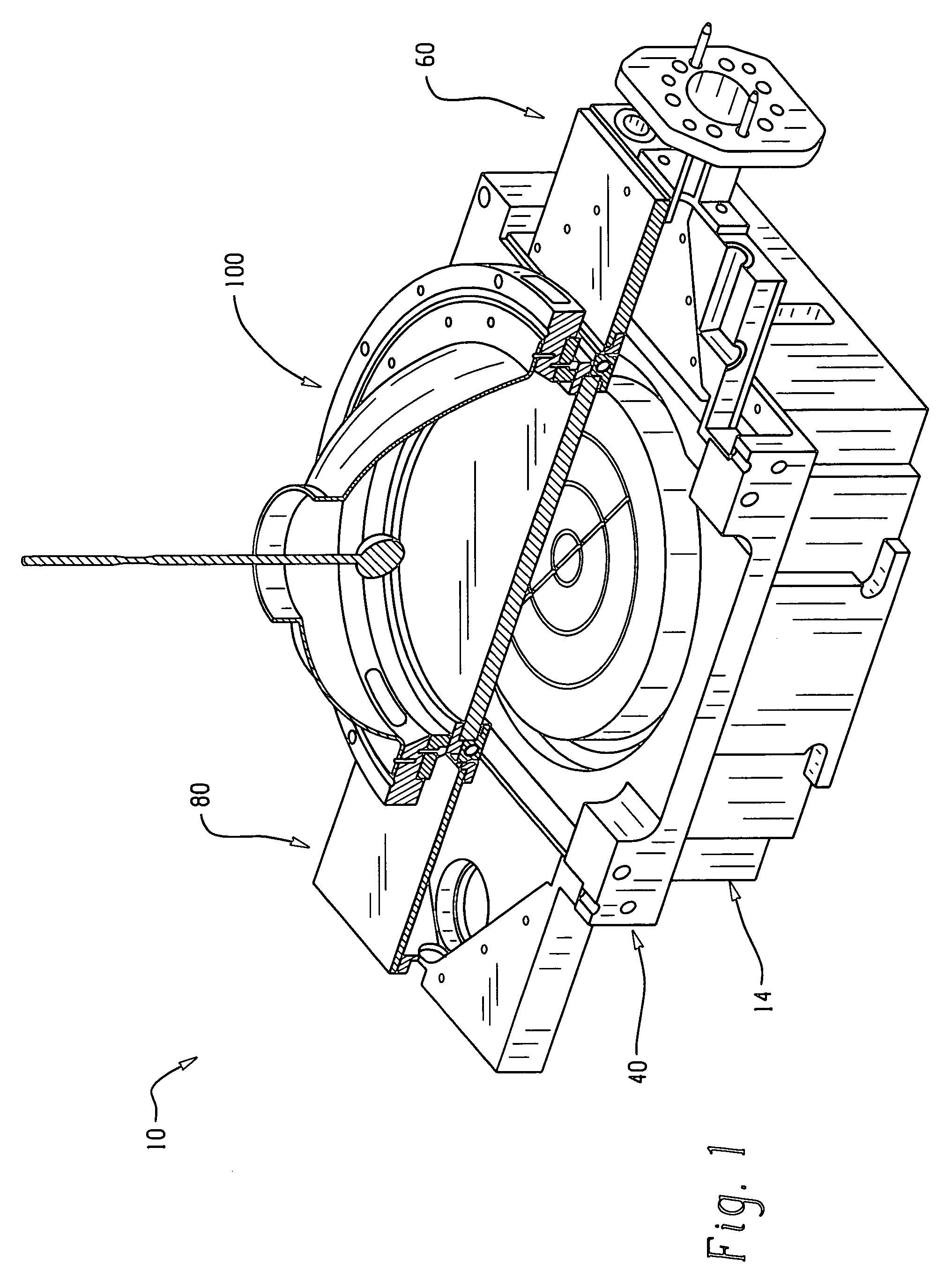
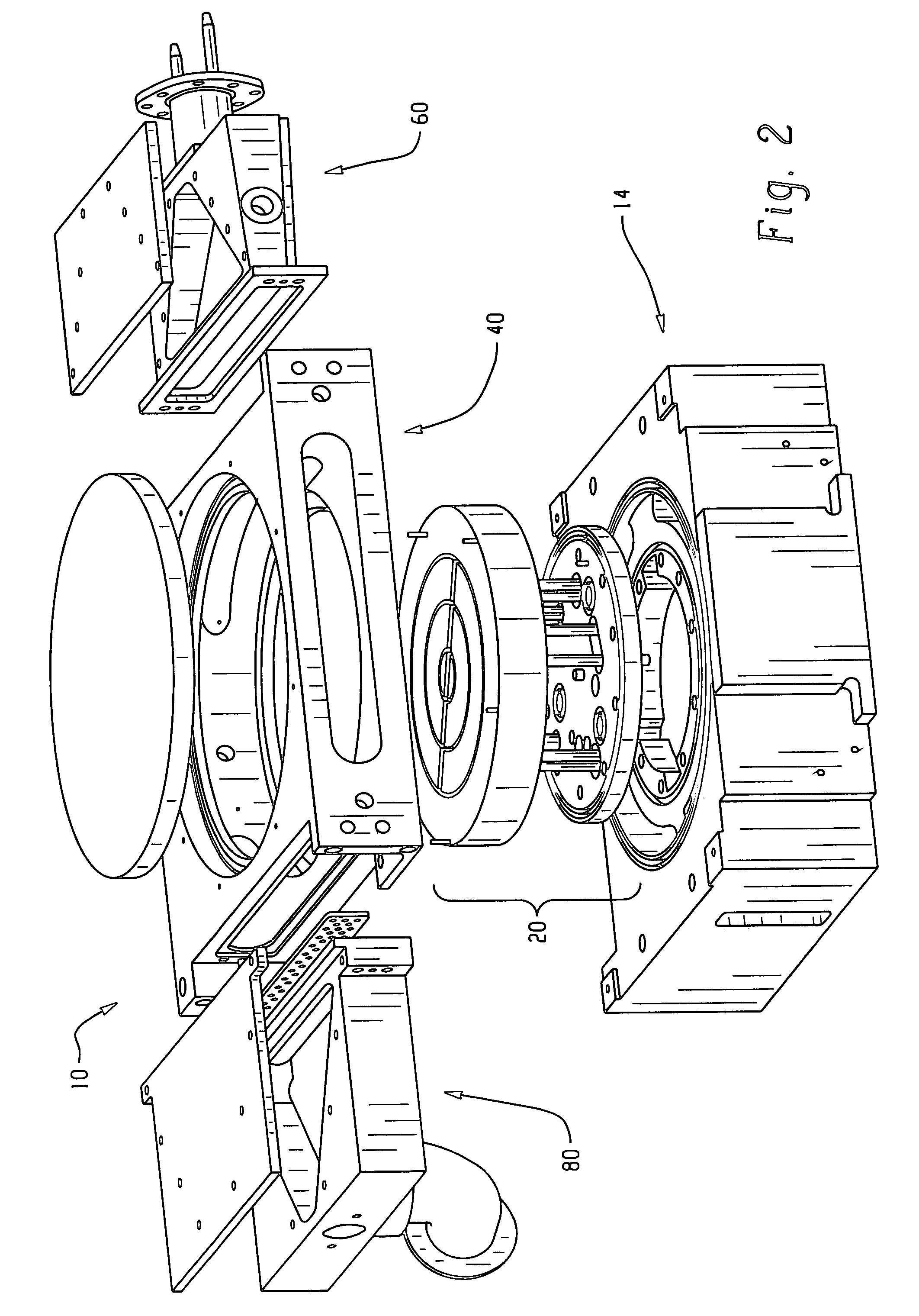
[0057]In this example, a bulk strip photoresist removal process was employed in a plasma asher employing a cross flow reactor assembly and compared to conventional axial flow reactor assemblies constructed for the same application. Substrates were coated with photoresist and exposed to the bulk photoresist removal process. The axial flow plasma reactor assemblies included a GES plasma asher and an MCU plasma asher, both of which are commercially available from the Axcelis Technologies Corporation. The cross flow reactor assembly included the use of a flow restrictor disposed in the exhaust manifold assembly as previously described. The flow restrictor employed was a planar plate having a circular passageway configuration similar to the flow restrictor shown in FIG. 15. The flow restrictor was installed in the recess 88 of the exhaust manifold assembly 80 with the passageway pattern oriented toward the top of the process chamber 40 such that the lower row of circular passageways was ...


PUM

PropertyMeasurementUnit
Fractionaaaaaaaaaa
Fractionaaaaaaaaaa
Fractionaaaaaaaaaa

Abstract

A reactor assembly and processing method for treating a substrate generally includes a base unit, a chuck assembly, a process chamber, an inlet manifold assembly and an exit manifold assembly. The inlet manifold assembly is in fluid communication with a first opening of the process chamber, wherein the inlet manifold assembly comprises a flow-shaping portion adapted to laterally elongate a gas and / or a reactant flow into the process chamber. The exhaust manifold assembly in fluid communication with a second opening of the process chamber and is diametrically opposed to the inlet manifold assembly. The process includes flowing a gas and / or reactive species into the process chamber of the reactor assembly in a direction that is about planar with the substrate surface providing improved uniformity and increased reactivity.

Description

BACKGROUND OF THE INVENTION[0001]The present disclosure relates to a reactor assembly for processing substrates and more particularly, to a distribution system for flowing gases and / or reactants into and out of the reactor assembly.[0002]In many semiconductor fabrication processes, process gas is introduced into a process chamber of a reactor assembly through a gas distributor. Plasma may be formed from the gas to etch features on the substrate, deposit layers of material on the substrate, and the like. Gaseous byproducts formed during processing are exhausted from the process chamber via an exhaust system. In etching processes, the uniformity of the shape and size of features across the substrate is affected by the distribution of gaseous species across the substrate, especially when the size and spacing of the etched features become smaller. Similarly, in deposition processes, the thickness and composition of the deposited layer can vary across the surface of the substrate dependi...

Claims


Application Information

Patent Timeline
IPC IPC(8): C23C16/48C23F1/10H01L21/306C23C16/52C23F1/00C23C16/44H01L21/3065C23C16/455H01L21/31
CPCC23C16/45504C23C16/455H01L21/67017C23C16/45561
Inventor KINNARD, DAVID WILLIAMFERRIS, DAVID
Owner LAM RES CORP
Why Eureka
Try Eureka