[0063]FIG. 10 illustrates a second embodiment of a feedback subsystem 86, employing a set of position detection sensors 138, and row and column detection circuitry 140,142, respectively. The position detection sensors 138 may be pressure sensitive, resistivity sensitive, or capacitivity sensitive.
[0064]One method of detecting the position of bodies of fluid 22a, 22b (e.g., drops or droplets) involves measuring the resistance between adjacent sensor electrodes. If the sensor electrodes are in electrical contact with the fluid body 22a, 22b, the application of a voltage pulse to one sensor electrode can be detected by an adjacent sensor electrode if the body of fluid 22a, 22b is in contact with both sensor electrodes. If the body of fluid 22a, 22b is not in contact with both sensor electrodes, the resistance of the air/immiscible fluid between the electrodes I too great for a pulse to be detected.
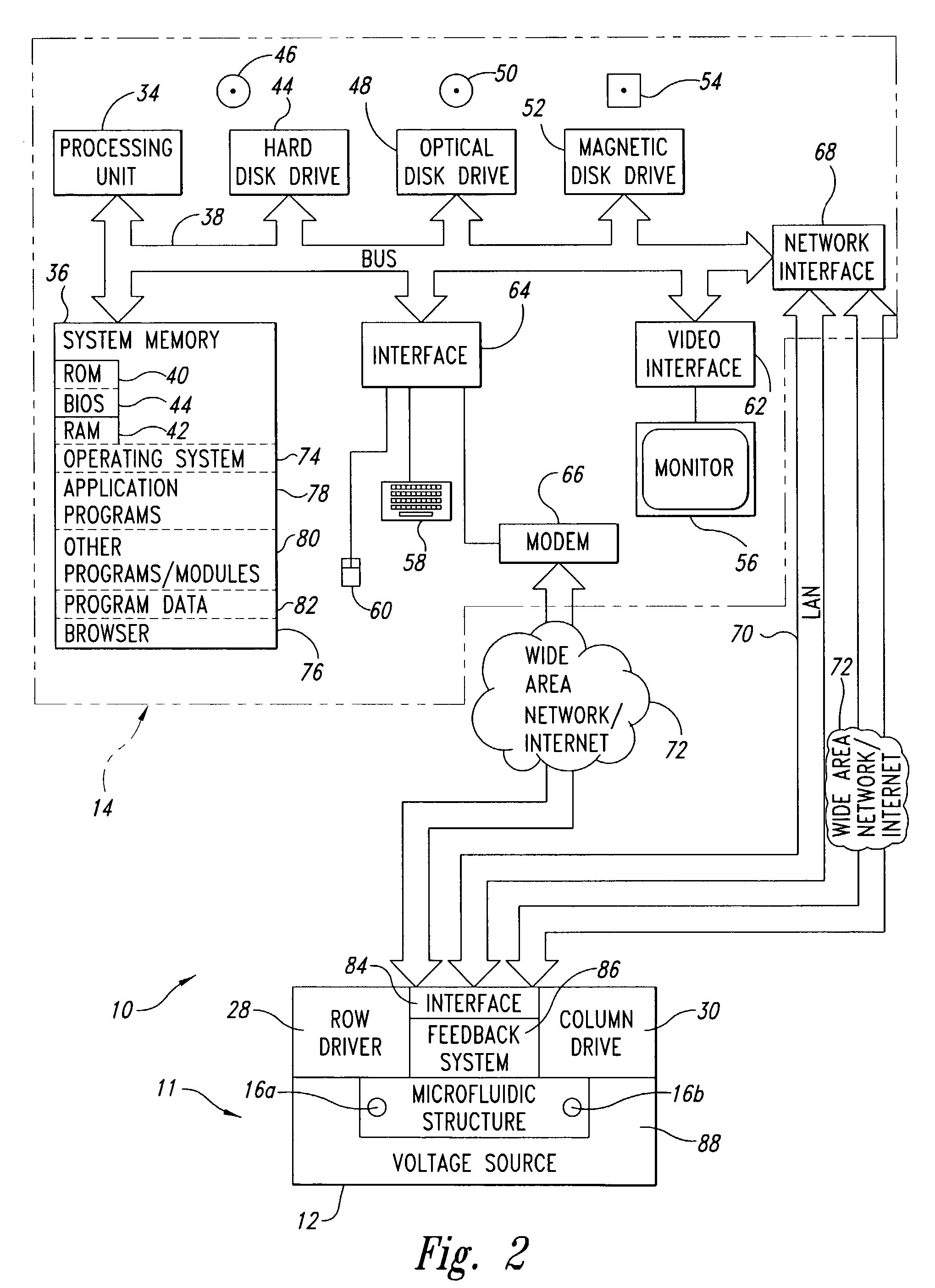
[0065]The feedback subsystem 86 may employ a TFT array of sensor electrodes by activating a row of sensor electrodes 140 and then pulsing the potential of one column of sensor electrodes 142 at a time, while measuring the potential at the adjacent sensor electrodes. By raster scanning through all rows and columns, data representing the location of bodies of fluid 22a, 22b can be provided to the active matrix display 56 to visually indicate the current location of the bodies of fluid 22a, 22b and/or to provide a feedback signal to control the drive electrodes 26 to adjust the motion of the bodies of fluid 22a, 22b. More generally, for any sensor system, the row and column detection circuitry 140, 142 receive electrical signals from the position detection sensors 138 and provide position information 144 to the computing system 14, identifying the position of one or more bodies of fluid 22a, 22b in the microfluidic structure 12. Suitable row and column detection circuitry 140, 142 is disclosed in U.S. Pat. No. 5,194,862 issued Mar. 16, 1993 to Edwards. Suitable processing software (e.g. application programs 78) may be loaded into the system memory 36 of the computing system 14 to provide an animated display of the bodies of fluid 22a, 22b, and/or control the drive electrodes 26 of the microfluidic structure 12 via drive signals 136 as discussed more fully below.
[0066]As an open platform, the microfluidic system 10 allows reconfiguration of protocols through the use of software to specify the potential of each electrode 26, 32, and thereby control the motion of individual bodies of fluid 22a, 22b. A protocol for a particular assay may be controlled by using commercial, off-the-shelf software, for example video editing software, to create an “animation” to charge the electrodes 26, 30 adjacent to a droplet edge sequentially so that motion occurs. Fluid bodies 22a, 22b with a lateral dimension (i.e., a dimension in the plane of the liquid/solid interface) allowing coverage of some portion of the dielectric layer 116 overlying at least two drive electrodes 26 can be moved by (1) addressing the electrodes with 8-bit control on the electrode potential that already exists in flat panel displays to provide 256 gray levels of light intensity and (2) addressing the display electrodes with control over the 3 display columns associated with Red, Green, and Blue for a display pixel so that microfluidic control can be provided with a factor of 3 increase over the display pixel density. (E.g., 1280×1024×3 for SXGA format).
[0067]The microfluidic structure 12 may employ TFT AMLCD technology and/or electrode addressing, and may thus use commercially available animation software (e.g., application programs 78). The use of an array of many drive electrodes 26 to control drops larger in diameter than one or two drive electrodes 26 has not been previously reported, while the microfluidic structure 12 may utilize multiple drive electrodes 26 to manipulate larger drops, for example causing a large drop to divide into two or more smaller drops. In particular, a ratio of at least two drive electrodes to an area covered by a fluid body 22a, 22b (i.e., electrowetted area) allows the splitting of the fluid body 22a, 22b into two fluid bodies. A ratio of at least three drive electrodes 26 to an area covered by a fluid body 22a, 22b allows particularly effective fine grain control of the fluid body 22a, 22b.
[0068]While commercial animation software may be used to generate protocols, this may in some cases require trial-and-error programs to ensure robust droplet control, especially for some droplet-splitting processes where surface tension forces marginally vary around the droplet edge. As discussed above, the feedback subsystem 86 may be integrated to detect the location of droplets, and to ensure robust droplet control, for example, via closed-loop feedback control. This will prove beneficial for users with samples having varying physical properties because a single control algorithm will not be appropriate for every sample. Customized software for generating animations within closed-loop feedback (i.e., real time control) to verify and direct droplet location may prove a major feature of the microfluidic system 10 platform as the system gains wide acceptance.
[0069]FIG. 11 shows a method 200 of operating the microfluidic system 12. In act 202, an end user produces an executable animation file using the user interface of an animation software program or package. In some embodiments, the animation software may be standard, unmodified commercially available animation software suitable for producing animations or videos for display on active matrix displays. The animation software may stored on any computer-readable media 46, 50, 54 (FIG. 2) and may be executed on the computing system 14 (FIG. 1), or on some other computing system (not shown).
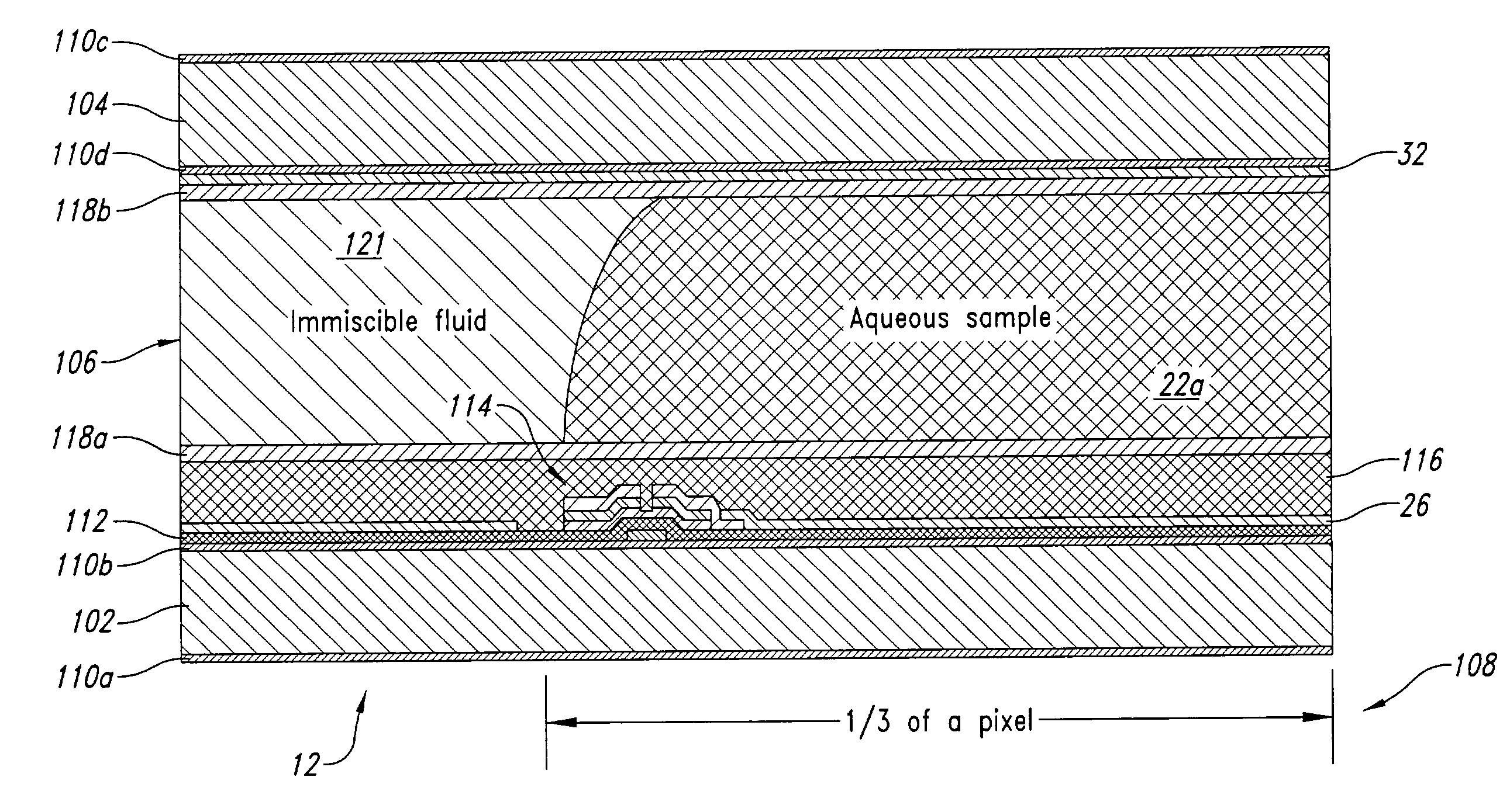
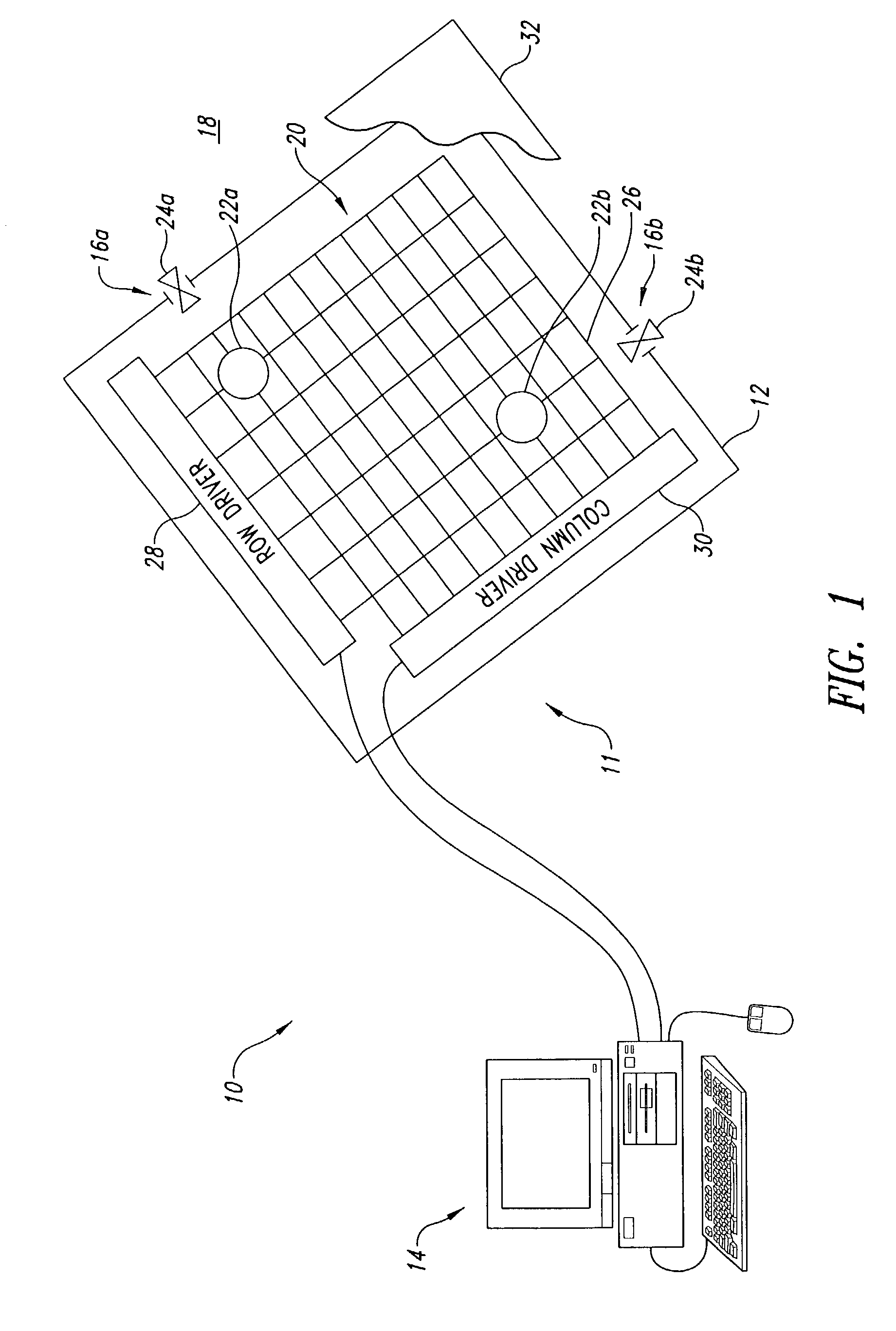
[0070]In act 204, the computing system 14 executes the animation file. In response, the computing system 14 provides drive signals to the transistors 114 (FIG. 3) by way of the row and column drivers 28, 30 (FIG. 1) in act 206. In act 208, the transistors 114 selectively couple the drive electrodes 26 to one or more voltage sources 88. In response, a respective potential is successively applied to respective portions of the dielectric layer 116, causing the fluid body 22a, 22b to move from drive electrode 26 to drive electrode 26, in act 210.
[0071]FIG. 12 shows an additional method 230 of operating the microfluidic system 12. In act 232, the position feedback sensors sense the actual position of one or more bodies of fluid 22a, 22b. In act 234, the position feedback sensor produces position feedback signals. In act 236, the computing system 14 receives the position feedback signals. In act 238, the processing unit 34 of the computing system 14 provides position feedback signals to the active matrix display 56. In some embodiments, the position feedback signals require no modification or preprocessing to drive the active matrix display 56, for example, where the position feedback signals are provided by an active matrix of position detection sensors 138. In other embodiments, the position feedback signals may require preprocessing, for example, where the feedback signals a provided by an array of image sensors such as a camera 132. Act 240 can be performed in concert with act 242 to display the actual and desired locations and/or flow paths at the same time.
[0072]In act 240 the active matrix display 56 displays the actual position and/or flow path of one or more of the fluid bodies 22a, 22b. In act 242, the processing unit 34 of the computing system 14 drives the active matrix display 56 using the executable animation file to display a desired position and/or desired flow path of one or more bodies of fluid 22a, 22b. In some embodiments, the executable animation file requires no modification or preprocessing to drive the active matrix display 56, for example, where the executable animation file was generated with standard animation software.
[0073]FIG. 13 shows a further method 250 of operating the microfluidic system 12. In particular, the microfluidic system 10 employs the position feedback subsystem 86 to adjust the operation of the microfluidic system 10 based on position feedback. For example, in act 252, the computing system 14 determines a difference between an actual position and a desired position. In step 254 the computing system 14 adjusts a next set of drive signals based on the determined difference. For example, the computing system 14 may delay some signals, or change the frequency of electrode 26, 32 operation along one or more flow paths. In act 256, the computing system 14 provides the adjusted next set of drive signal to the transistors 114 to drive the drive electrodes 26, adjusting the movement of one or more of the bodies of fluid 22a, 22b from a previously defined flow path. Thus, the computing system 14 may compensate for inconsistencies in the physical structure of the microfluidic structure 12 (e.g., differences in drive electrodes 26, transistors 114, and/or across the fluid compatibility layer 118), and/or different properties of the fluid bodies 22a, 22b, and/or any other unexpected or difficult to estimate operating parameters.
[0074]FIG. 14 shows a further method 260 of operating the microfluidic system 12. In act 262, the computing system 14 converts the received position feedback signals into an executable animation file. In step 264, the processing unit 34 drives the active matrix display 56 according to the converted executable animation file to display an animation of the actual flow path of one or more of the bodies of fluid 22a, 22b.
[0075]The above-described methods can be used with each other, and the order of acts may be changed as would be apparent to one of skill in the art. For example, the method 260 can generate an animation of the actual flow path to be displayed in act 240 of method 230. Also for example, the method 250 can be combined with method 260 to display an adjusted position and/or flow path before providing the adjusted next set of drive signal to the transistors 114. The described methods can omit some acts, can add other acts, and can execute the acts in a different order than that illustrated, to achieve the advantages of the invention.
[0076]FIG. 15 shows a display 270 on a screen of the active matrix display 56 (FIGS. 1 and 2) of a set of desired flow paths 272, 274, actual flow paths 276, 278, desired positions D1, D2 and actual positions A1, A2 for a two bodies of fluid 22a, 22b, respectively, in the microfluidic structure 12 in accordance with the methods discussed above. In particular, the body of fluid 22a enters via a first port 16a, and is directed along a desired flow path 272 to an exit port 16b. As illustrated by the actual flow path 276, the body of fluid 22a has deviated from the desired flow path 272 for any of a variety of reasons, and is at the actual position A1 instead of the desired position D1 at a given time. The second fluid body 22b enters via a port 16c and is directed along a desired flow path 274, in order to combine with the first fluid body 22a at a point 280. As illustrated by the actual flow path 278, the second fluid body 22b is following the desired flow path 274 as directed and the actual position A2 corresponds with the desired position D2. The computing system 14 can make appropriate adjustment in the drive signals to adjust the speed and/or direction of the first and/or second fluid bodies 22a, 22b to assure that the first and second fluid bodies 22a, 22b combine at the point 280, which may, or may not have an additional reactant or other molecular components.
[0077]Much of the detailed description provided herein is disclosed in the provisional patent application; most additional material will be recognized by those skilled in the relevant art as being inherent in the detailed description provided in such provisional patent application or well known to those skilled in the relevant art based on the detailed description provided in the provisional patent application. Those skilled in the relevant art can readily create source based on the detailed description provided herein.
[0078]Although specific embodiments of and examples for the microfluidic system and method of the invention are described herein for illustrative purposes, various equivalent modifications can be made without departing from the spirit and scope of the invention, as will be recognized by those skilled in the relevant art. The invention may utilize thin film transistor active matrix liquid crystal display technology to manipulate small samples of fluid for chemical, biochemical, or biological assays with no moving parts. The platform utilizes existing active matrix addressing schemes and commercial-off-the-shelf animation software such as video editing software to program assay protocols. The teachings provided herein of the invention can be applied to other microfluidic platforms, not necessarily the exemplary active matrix microfluidic platform generally described above. The various embodiments described above can be combined to provide further embodiments.
[0079]Other teachings on electrowetting include G. Beni and M. A. Tenan, “Dynamics of Electrowetting Displays,” J. Appl. Phys., vol. 52, pp. 6011–6015 (1981); V. G. Chigrinov, Liquid Crystal Devices, Physics and Applications, Artech House, 1999; E. Lueder, Liquid Crystal Displays, Addressing Schemes and Electro-Optical Effects, John Wiley & Sons, 2001; M. G. Pollack, R B Fair, and A. Shenderov, “Electrowetting-based actuation of liquid droplets for microfluidic applications,” Appl. Phys. Left., vol. 77, number 11, pp. 1725–1726 (2000); and P. Yeh and C. Gu, Optics of Liquid Crystal Displays, John Wiley & Sons, 1999.
[0080]All of the above U.S. patents, U.S. patent application publications, U.S. patent applications, foreign patents, foreign patent applications and non-patent publications referred to in this specification and/or listed in the Application Data Sheet, including but not limited to U.S. No. 60/333,621, filed Nov. 26, 2001, are incorporated herein by reference in their entirety.
[0081]Various changes can be made to the invention in light of the above-detailed description. In general, in the following claims, the terms used should not be construed to limit the invention to the specific embodiments disclosed in the specification and the claims, but should be construed to include all microfluidic platforms that operate in accordance with the claims. Accordingly, the invention is not limited by the disclosure, but instead its scope is to be determined entirely by the following claims.