Electrostatic separator

a technology of electrostatic separator and separator plate, which is applied in the direction of liquid fuel feeder, centrifuge, water/sludge/sewage treatment, etc., can solve the problems of difficult maintenance, complex and voluminous construction of the prior art electrostatic separator plate, etc., and achieves simple and compact structure and easy maintenance

Inactive Publication Date: 2007-01-16
SULZER MANAGEMENT AG
View PDF18 Cites 20 Cited by
  • Summary
  • Abstract
  • Description
  • Claims
  • Application Information

AI Technical Summary

Benefits of technology

[0012]It is an object of the invention to present an electrostatic separator containing a vessel, which separator has a construction that is considerably simpler and more compact compared to prior art separators. The electrostatic separator shall also be operatively reliable and promote an easy maintenance thereof.BRIEF DESCRIPTION OF THE INVENTION

Problems solved by technology

Thus, prior art electrostatic separators show a complicated and voluminous construction, and are also difficult to maintain.

Method used


Image

  • Electrostatic separator
  • Electrostatic separator
  • Electrostatic separator

Examples


first embodiment

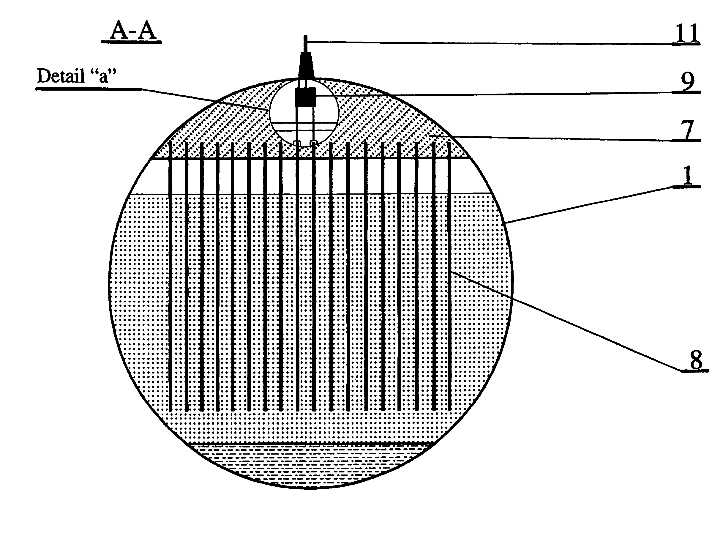
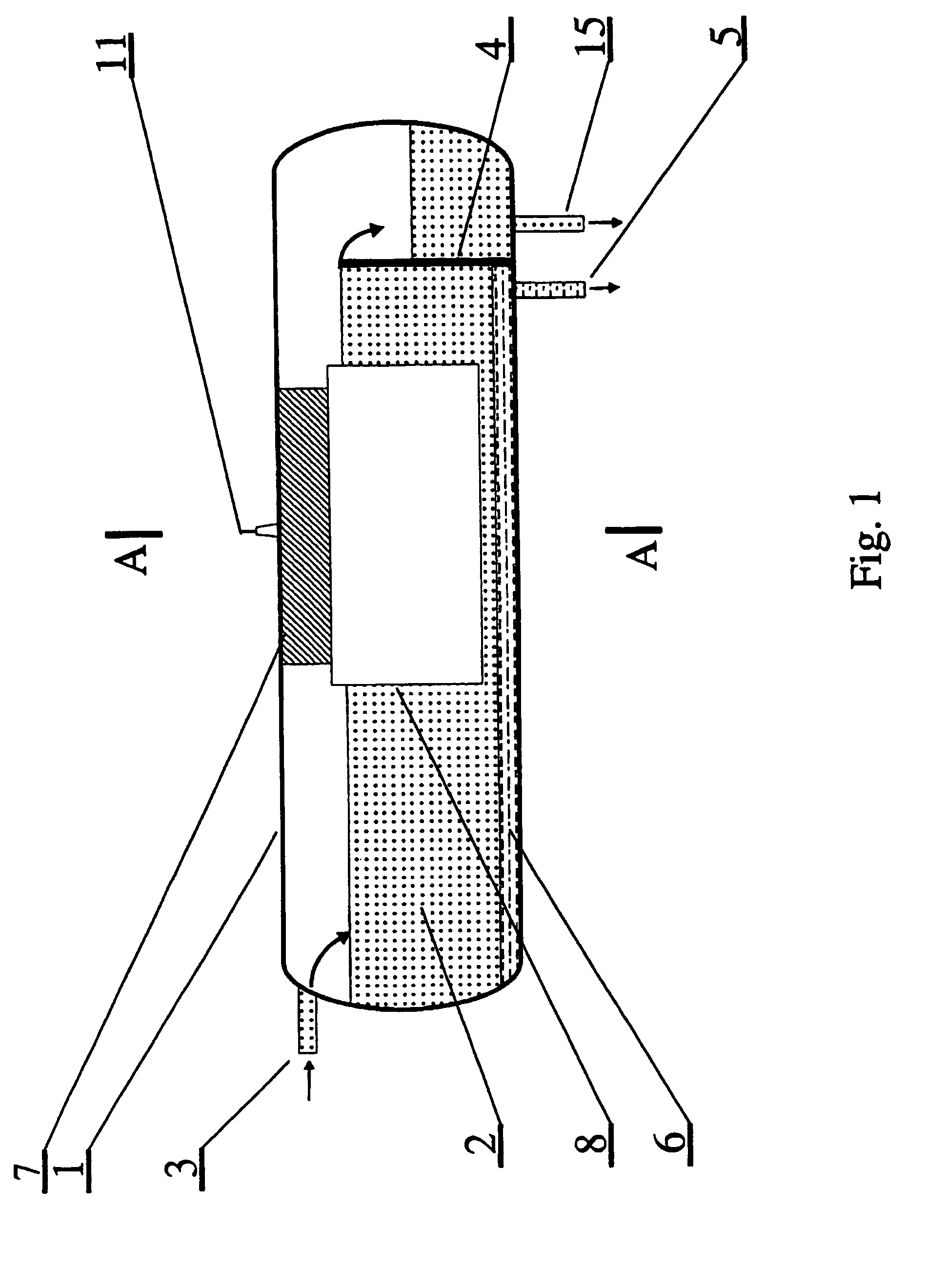
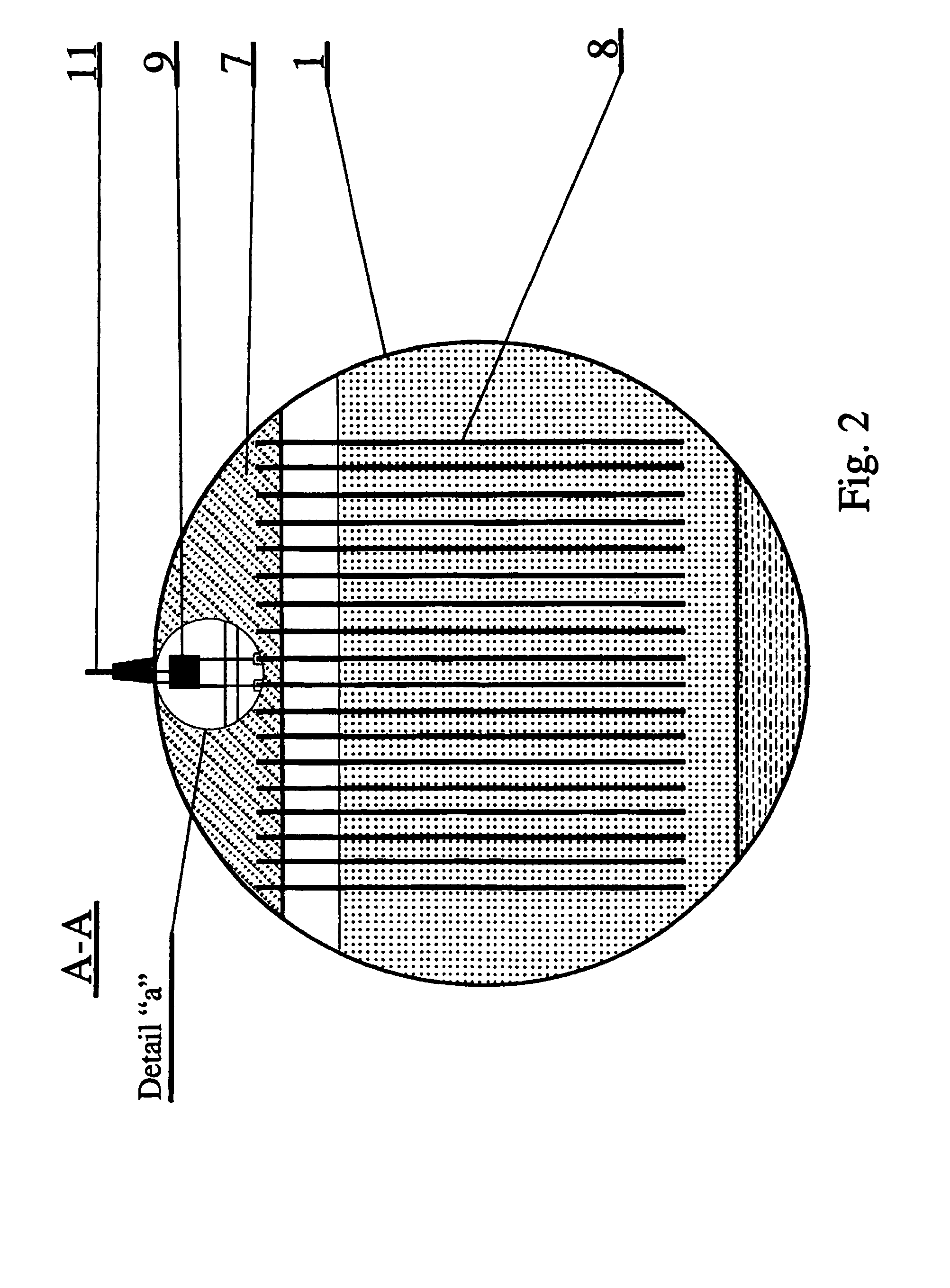
[0029]As can be seen in more detail in FIGS. 2 and 3, according to the invention, one end of the low voltage winding of the transformer 9 is connected to an external low voltage terminal 11, while the other end is connected with the vessel wall. The ends of the high voltage winding 12 of the transformer 9 are connected via voltage busbars 13, which are embedded in the material of the frame 7, with conducting elements 14 made of flat channel bars, by electric connection of the channel back with the appropriate bus. In each conducting element 14, which is located in the insulating material of the frame 7, in the gap formed between the flanges of the channel bar and in a groove located in the frame 7, directly under the gap of the channel, there is placed a conducting plate 8 of the electrode system. Between the outer surface of this plate and the inner surface of the conducting element 14 there is an insulating layer of the frame 7, whose thickness corresponds to the difference in the...

second embodiment

[0030]In the invention, as shown in FIGS. 4 and 5, a system or set of electrodes is fixed in the conducting elements 14 in the frame 7, which are supplied with high voltage of the sane sign. One end of the high voltage winding 12 is connected, through a busbar 13 and the conducting element 14, with conducting plates 8 or with conducting plates with an insulating layer 8a, while the second end is connected to a coupling element 16, located inside the frame 7, in close proximity of the vessel wall, so that the capacitance between the coupling element 16 and the wall of the vessel 1 is greater than the capacitance between each pair of the conducting plates 8 of the electrode system, formed by the conducting plate 8 or the conducting plate with the insulating layer 8a, and an earthing electrode 17. The earthing electrodes 17 in the form of substantially vertically arranged plates or sheets are located between the conducting plates 8 or supply electrodes and they are connected with the v...


PUM

PropertyMeasurementUnit
operating frequencyaaaaaaaaaa
voltageaaaaaaaaaa
insulatingaaaaaaaaaa

Abstract

An electrostatic separator intended for separation of liquid phase systems, made up of mixtures of liquids of various electrical permittivity. In particular, the separator is intended for separation of an oil-and-water emulsion. The electrostatic separator contains a vessel, inside which there is suspended a system of electrodes energized from an external voltage source. The electrode system comprises at least one pair of conducting plates (8), which is attached to a supporting frame (7) and electrically connected with the high voltage winding of a feeding transformer (9), which is placed in the supporting frame (7). The supporting frame (7) is preferably a casting of an insulating material. The conducting plates (8) of the electrode system are preferably connected to the winding of the feeding transformer (9) through a capacitive electrical connection.

Description

CROSS-REFERENCE TO RELATED APPLICATIONS[0001]This application claims priority to Polish patent application 351182 filed 13 Dec. 2001 and is the national phase under 35 U.S.C. §371 of PCT / IB02 / 05358.[0002]1. Technical Field[0003]The present invention relates to an electrostatic separator intended for separation of liquid phase systems, which are mixtures of liquids of different electrical permittivity. In particular, the electrostatic separator contains a vessel, inside which there is suspended a system or set of electrodes energised by means of an external voltage source.[0004]Since the invention is particularly applicable to electrostatic separators for separation of water from oil in oil-and-water emulsions, it will be described with reference to such an application. However, it should be understood that the invention is applicable to all kinds of electrostatic separation applications intended for separation of liquid phase systems.BACKGROUND OF THE INVENTION[0005]Electrostatic se...

Claims


Application Information

Patent Timeline
Patent Type & Authority Patents(United States)
IPC IPC(8): B01D17/06B01D17/02B03C5/02
CPCB01D17/0211B03C5/02B03C11/00B01D17/04B01D17/06B03C2201/02
Inventor NILSEN, PAL JAHREPIASECKI, WOJCIECH
Owner SULZER MANAGEMENT AG
Why Eureka
Try Eureka