Exhaust gas purifying system for engine

a technology of exhaust gas purification system and engine, which is applied in the direction of machines/engines, electrical control, separation processes, etc., can solve the problems of deteriorating engine emission, unable to raise the temperature of the hc trap catalyst, etc., and achieves the effect of increasing the excess air ratio and increasing the heat quantity generated

Inactive Publication Date: 2007-01-23
NISSAN MOTOR CO LTD
View PDF13 Cites 2 Cited by
  • Summary
  • Abstract
  • Description
  • Claims
  • Application Information

AI Technical Summary

Benefits of technology

[0022]a control unit being programmed to: upon activating the HC trap catalyst after the engine is started, control a target excess air ratio to a preset value smaller than a normal value to which the target excess air ratio is controlled when the HC trap catalyst is activated, to thereby rise an exhaust gas temperature; and increase the target excess air ratio as the temperature of the HC trap catalyst rises, to thereby increase a heat quantity generated upon oxidation of the HC trapped by the HC trap catalyst.

Problems solved by technology

Even through the heating of the HC trap catalyst using the light oil adding device is attempted immediately after start-up of an engine in order to quickly activate the HC trap catalyst, the temperature of the HC trap catalyst will fail to be sufficiently raised.
This results in deteriorating the emission from the engine.

Method used


Image

  • Exhaust gas purifying system for engine
  • Exhaust gas purifying system for engine
  • Exhaust gas purifying system for engine

Examples


Embodiment Construction

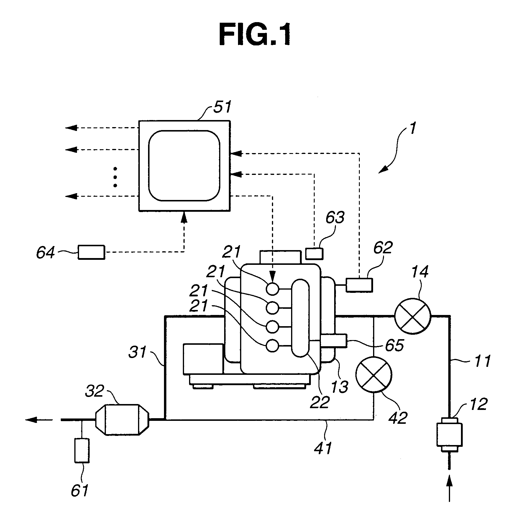
[0044]Referring to FIGS. 1–16, an exhaust gas purifying system, according to a first embodiment of the present invention, now is explained. In this embodiment, the system is applied to a direct injection diesel engine, referred to hereinafter merely as an engine. As illustrated in FIG. 1, engine 1 includes intake passage 11 into which intake air is introduced. The intake air flowing into an inlet portion of intake passage 11 is filtered at an air cleaner, not shown, where dust in the intake air is removed. Airflow meter 12 is disposed in intake passage 11 downstream of the air cleaner and measures a quantity of intake air flowing therethrough. The intake air passing through the air cleaner and airflow meter 12 flows into surge tank 13 via intake throttle valve 14. The intake air then flows into an intake manifold and is distributed to respective engine cylinders. Intake throttle valve 14 is electronically connected to electronic control unit, referred to hereinafter as ECU, 51. Inta...


PUM


Abstract

An exhaust gas purifying system for an engine, including a HC trap catalyst disposed in an exhaust passage and operative to trap HC contained in the exhaust gas, and a control unit being programmed to: upon activating the HC trap catalyst after the engine is started, control a target excess air ratio to a preset value smaller than a normal value to which the target excess air ratio is controlled when the HC trap catalyst is activated, to thereby rise an exhaust gas temperature; and increase the target excess air ratio as the temperature of the HC trap catalyst rises, to thereby increase a heat quantity generated upon oxidation of the HC trapped by the HC trap catalyst.

Description

BACKGROUND OF THE INVENTION[0001]The present invention relates to a system for purifying exhaust gas emitted from an engine, which includes a HC trap catalyst for trapping hydrocarbons, referred to hereinafter as HC, and specifically, relates to a technology of allowing for rising a temperature of the exhaust gas and promoting activation of the HC trap catalyst using heat quantity of the exhaust gas.[0002]An exhaust gas purifying system for engines, which includes a HC trap catalyst is well known. The HC trap catalyst is constructed to trap HC contained in exhaust gas emitted from the engine when the HC trap catalyst is in a low temperature condition. Further, when temperature of the exhaust gas rises, the HC trap catalyst purifies nitrogen oxides, referred to hereinafter as NOx, which are contained in the exhaust gas, by the effect of HC trapped by the HC trap catalyst as a reducing agent. Here, if the HC trap catalyst traps sulfur components more than a given amount thereof, the H...

Claims


Application Information

Patent Timeline
Patent Type & Authority Patents(United States)
IPC IPC(8): F01N3/00F01N3/10F01N3/20B01D53/94F01N3/08F01N3/24F02D21/08F02D41/00F02D41/02F02D41/06
CPCF01N3/0814F01N3/0835F02D41/0255Y02T10/26F02D2200/0802F02D41/005Y02T10/12
Inventor MIURA, MANABU
Owner NISSAN MOTOR CO LTD
Why Eureka
Try Eureka