[0009]It is an object of the present invention to provide viewing apparatus that is omnidirectionally positionable. It is further an object to provide such apparatus that is retainable in a particular position without being manually held in that position. It is yet further an object to provide such apparatus that provides a means of precisely locating a specific area or feature on the body, particularly at the lower end of the
torso. It is still yet further an object to provide such apparatus that is safe to use.
[0012]It is important that the viewing device be very flexible in its positionability and be arrestable in a particular position, so that the person using the viewing device has both
hands free to perform other tasks with the aid of the viewing device. There are a number of suitable conventional means of attaching the viewing device to the support stand in a manner that provides the desired omni-positionability of the viewing device and that also allows the viewing device to be arrested in a particular position. For example, the support stand may include a bendable arm or a flexible support commonly referred to as a “gooseneck” that allows the viewing device to be moved along any number of imaginary axes, so as to provide precise positionability of the viewing device, the
light source and the
light beam pointer device. The mounting end of the gooseneck and the mounting base of the viewing device are equipped with a
mating fastening means, whereby any suitable fastening means, such as,
mating threaded fasteners, interference or friction-fit assemblies, hole-and-locking-pin assemblies, etc., may be used. The arm or the gooseneck provides a certain resistance to change of position once it is arrested in a position and thereby holds the position of the device in its arrested position.
[0013]A further key feature of the viewing apparatus is that the illumination devices, i.e., the general illumination device and the light beam pointer device, are an integral part of the apparatus and are attached either to the support stand or to the viewing device itself. The general illumination device is positioned to illuminate a broad area that includes the intended viewing site and the light beam pointer device is positioned to directly target a particular feature or small area within the intended viewing site. The illumination devices may be positionable independently of the viewing device, or may be mounted on the viewing device such that their positions are adjusted when the position of the viewing device is adjusted. Various configurations are included within the scope of the invention. For example, the general illumination device may be fixedly attached to the viewing device so as to be positionally adjustable in concert with the viewing device, and the light beam pointer device may be separately mounted and positionable independently of the position of the viewing device and general illumination device, or vice versa. Numerous means for attaching the general illumination device and the light beam pointer device to the support stand are suitable, such as the use of a clamp that is clamped to the freestanding support stand and securely holds the general illumination device and the light beam pointer device. The clamp allows both vertical and horizontal adjustment of the general illumination device and the light beam pointer device. A single clamp may be used to hold both the general illumination device and the light beam pointer device, whereby the direction of illumination of both illumination devices is adjusted during initial set-up of the viewing apparatus and a single adjustment of the clamp re-directs the direction of illumination from both illumination devices. In the alternative, separate clamps may be used to attach the general illumination device and the light beam pointer device individually to the support stand, thereby allowing each illumination device to be positioned independently according to need.
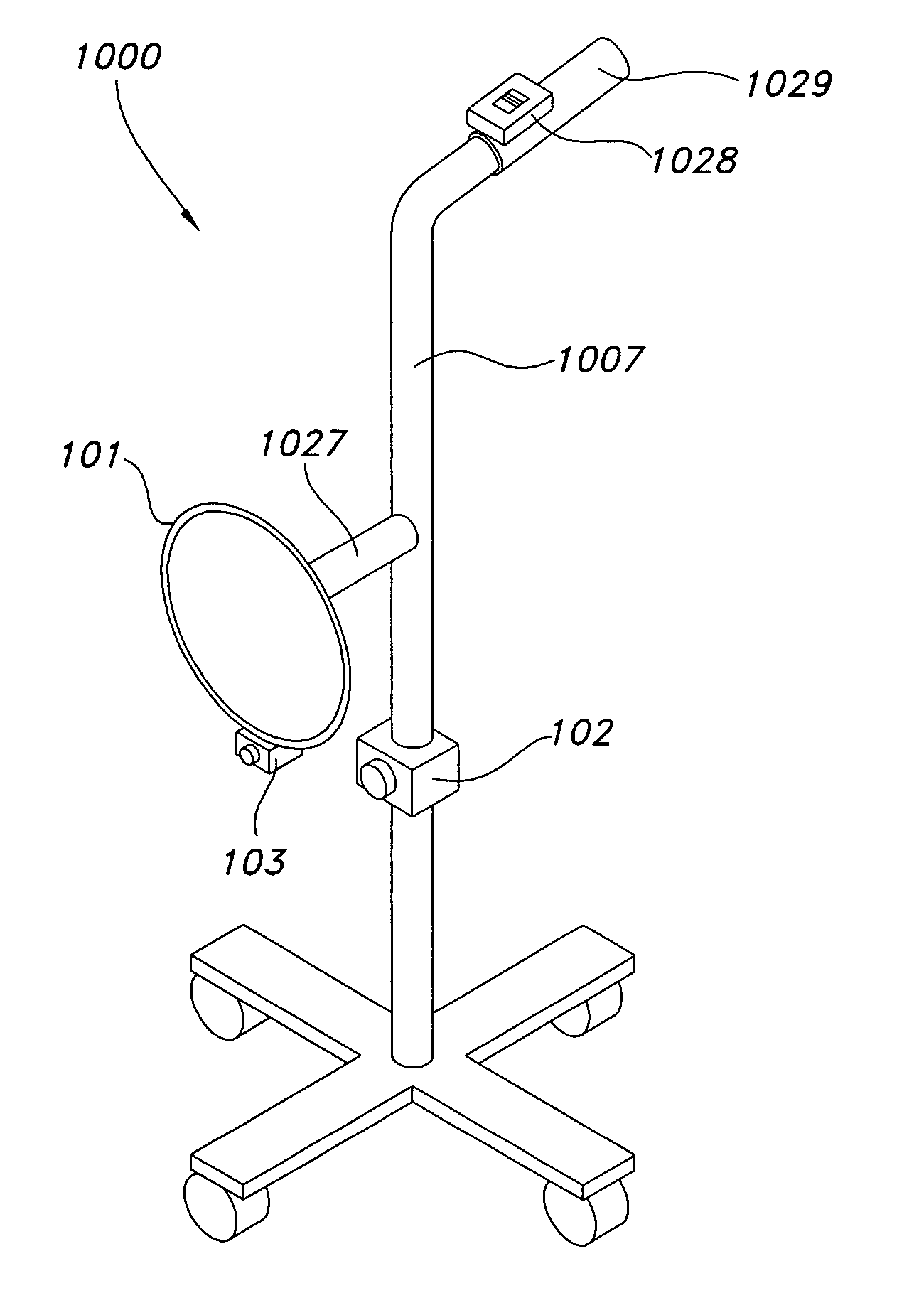
[0016]Depending on the particular intended venue of use for the viewing apparatus, more rugged types of support stands may be used as the freestanding support stand for the device. For example, for use in a hospital or clinic setting, one type of stand that is suitable for mounting the viewing device is similar to the stand that is used to support intravenous fluids in hospitals. Such a stand has a vertically adjustable center pole on a base of four supports fitted with casters, which may be lockable. The support stand is rugged, hard to tip over, and easily movable from one location to another. This type of conventional support stand is adapted to receive the viewing device and to provide the proper height for the intended viewing site. For example, the hook support for the
intravenous fluid bags is replaced with a gooseneck flexible arm or with another suitable type of joint, such as a
gimbal mechanism that is adapted to receive and retain the viewing device and that provides the desired omnidirectional positioning of the viewing device. The center pole may be height-adjustable or of a fixed height.
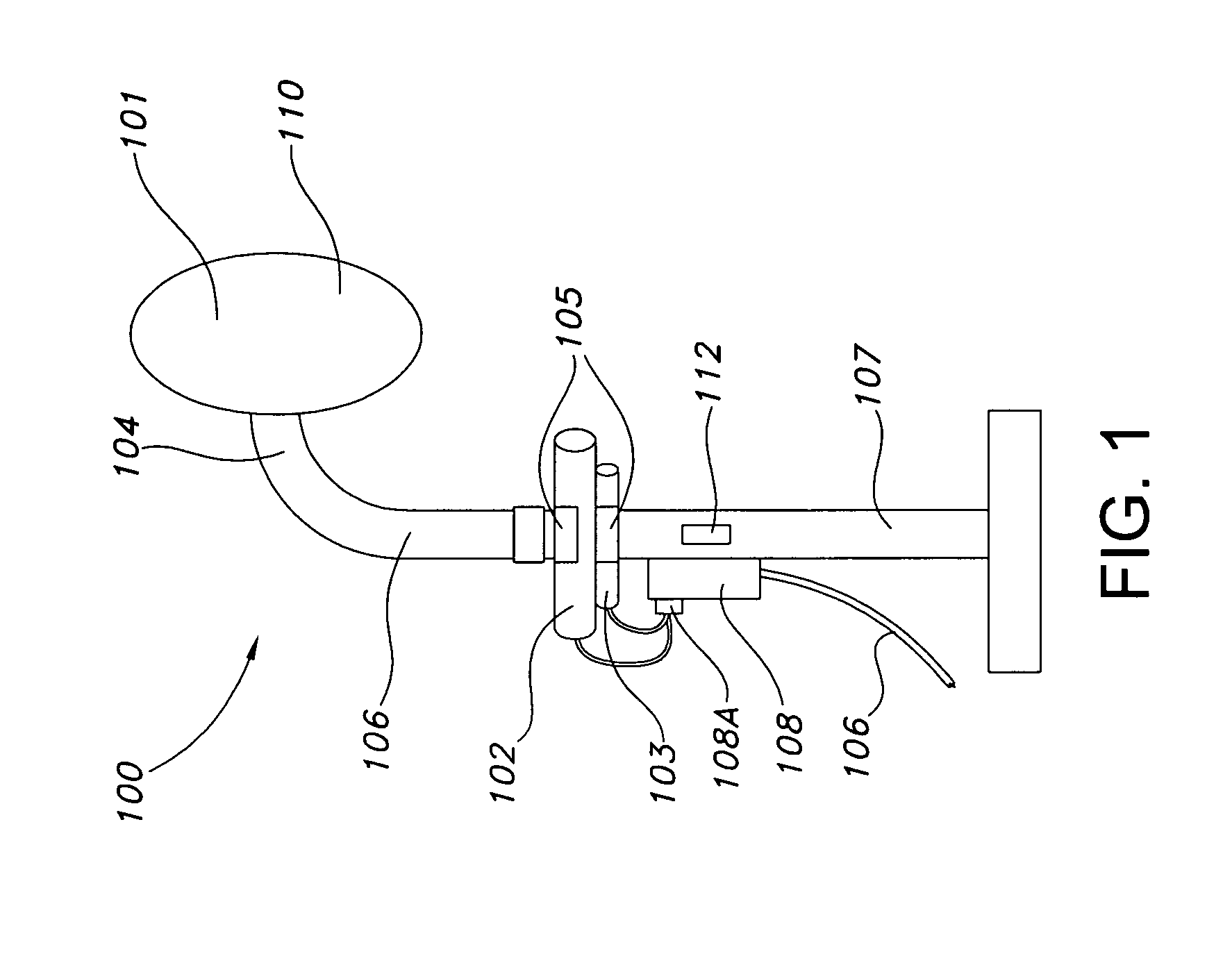
[0019]In an alternative embodiment of the present invention, the viewing device is a
video camera, analog or digital, with monitor. This embodiment of the invention is particularly useful in enabling an extremely obese person to view an otherwise visually inaccessible area of the body, such as the genital area. The camera is attached to the support stand in a manner similar to that of the general illumination device and the light beam pointer device. The camera may be mounted on the support stand as well, but may also be mounted instead separately from the support stand, to as to provide convenient and unencumbered viewing by the user of the apparatus. The camera is positionable to view the intended viewing site and sends a live image of the intended viewing site to the monitor for the person to view. The monitor may also provide a larger viewing area than a conventional mirror.
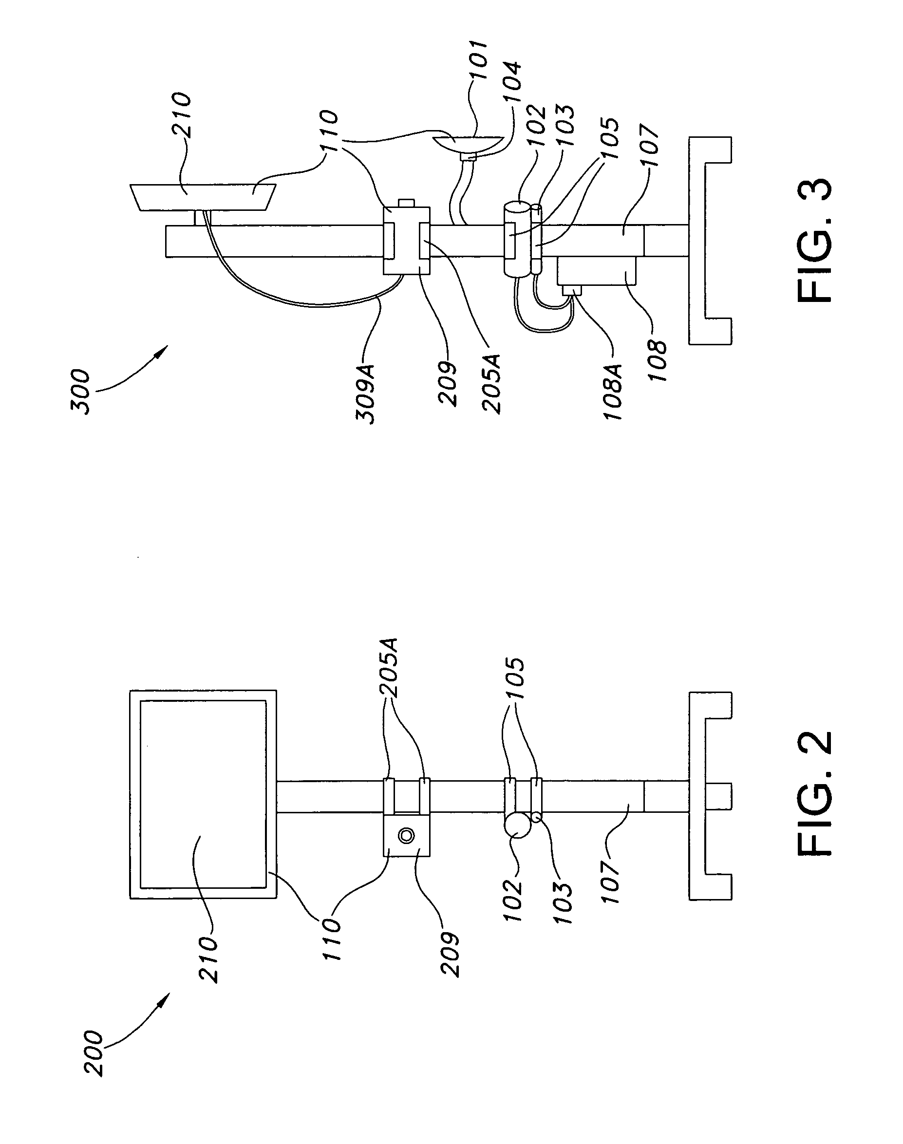
[0021]Similarly, another embodiment of the viewing device comprises a mirror
assembly that incorporates a camera with the lens assembled in the housing behind an aperture that is provided in the housing or in the mirror surface and a monitor mounted on the support stand. The camera transmits the image of the intended viewing site and sends the image to the monitor, thereby enabling a person to view the site.

