Particle control device and particle control method for vacuum processing apparatus

a vacuum processing and particle control technology, applied in vacuum evaporation coatings, chemical vapor deposition coatings, coatings, etc., can solve the problems of reducing the yield or reliability of semiconductor products, unable to detect particles during the processing of product wafers, and large number of defective wafers will be produced

Inactive Publication Date: 2007-01-23
HITACHI HIGH-TECH CORP
View PDF8 Cites 10 Cited by
  • Summary
  • Abstract
  • Description
  • Claims
  • Application Information

AI Technical Summary

Benefits of technology

[0012]According to an aspect of the present invention, there is provided a particle control device for use in a vacuum processing apparatus having a vacuum reactor, a gas delivery means for supplying processing gases to the vacuum reactor, and a sample table for placing and supporting a sample in the vacuum reactor, wherein the sample is subjected to vacuum processing in the apparatus. The particle control device includes a particle monitor for detecting particles floating inside the vacuum reactor; means for generating apparatus condition data indicating a condition of the vacuum processing apparatus; and data managing means for determining a component of the vacuum processing apparatus which has a high particle occurrence probability on the basis of particle data detected by the particle monitor and the apparatus condition data, thereby enabling the display of a component that has been determined to be a particle source.

Problems solved by technology

The particles which have adhered or fallen on the wafer surface cause imperfect etching and produce failures in subsequent processes, ultimately leading to a decreased yield or reduced reliability of the semiconductor products.
However, this method cannot detect particles during the processing of the product wafer.
With the conventional method, therefore, a large number of defective wafers will undesirably be produced until the particles are detected in the next inspection.
Although the floating particle detector disclosed in Japanese Patent Laid-open No. 2002-57143 is capable of detecting the presence of particles in the semiconductor manufacturing apparatus, it has difficulty in determining the particle sources.
Further, according to the system disclosed in Japanese Patent laid-open No. 6-201600, it is possible to detect on which wafer, in the one lot, the particles are present; however, this system also has difficulty in determining the particle sources.
That is to say, although it is possible with the conventional techniques to detect the presence of particles and when the particles appear, they have difficulty in determining the particle sources.
If the particle sources are not specified, it is difficult to determine what countermeasure to take, and it is impossible to provide a drastic solution to the occurrence of particles in the apparatus.
However, since such treatment is typically performed without knowing the cause of the occurrence of the particles, the particles will appear again soon after the cleaning in many cases.
Further, since it takes a considerably long period of time to effect cleaning of the vacuum reactor, the operation rate of the vacuum reactor is decreased, resulting in a reduction in the productivity of the manufacturing line.

Method used


Image

  • Particle control device and particle control method for vacuum processing apparatus
  • Particle control device and particle control method for vacuum processing apparatus
  • Particle control device and particle control method for vacuum processing apparatus

Examples


first embodiment

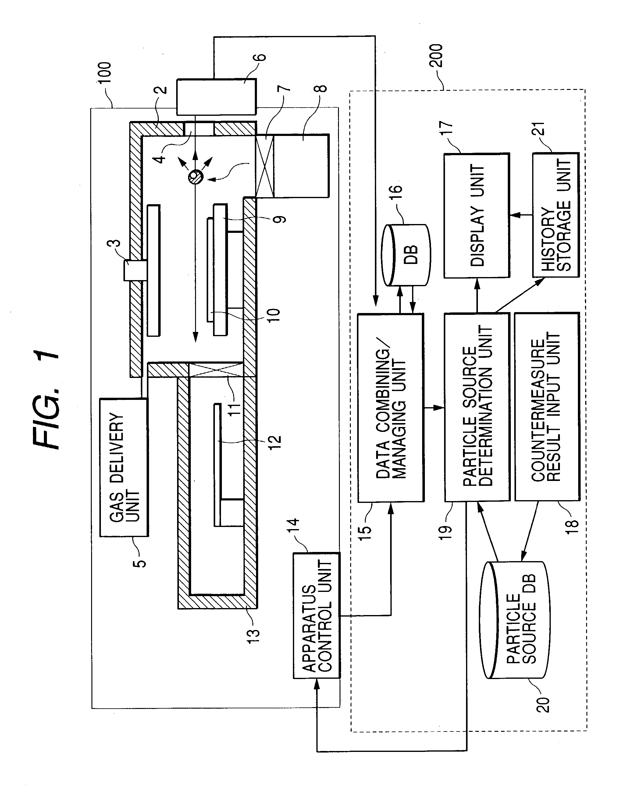
[0024]FIG. 1 is a diagram illustrating a particle control device according to the present invention. As shown in FIG. 1, a vacuum processing apparatus 100, such as a plasma etching apparatus, includes a vacuum reactor 2 and a plasma generation unit 3 having an antenna electrode and a coaxial line for supplying high frequency power to the antenna electrode (not shown).

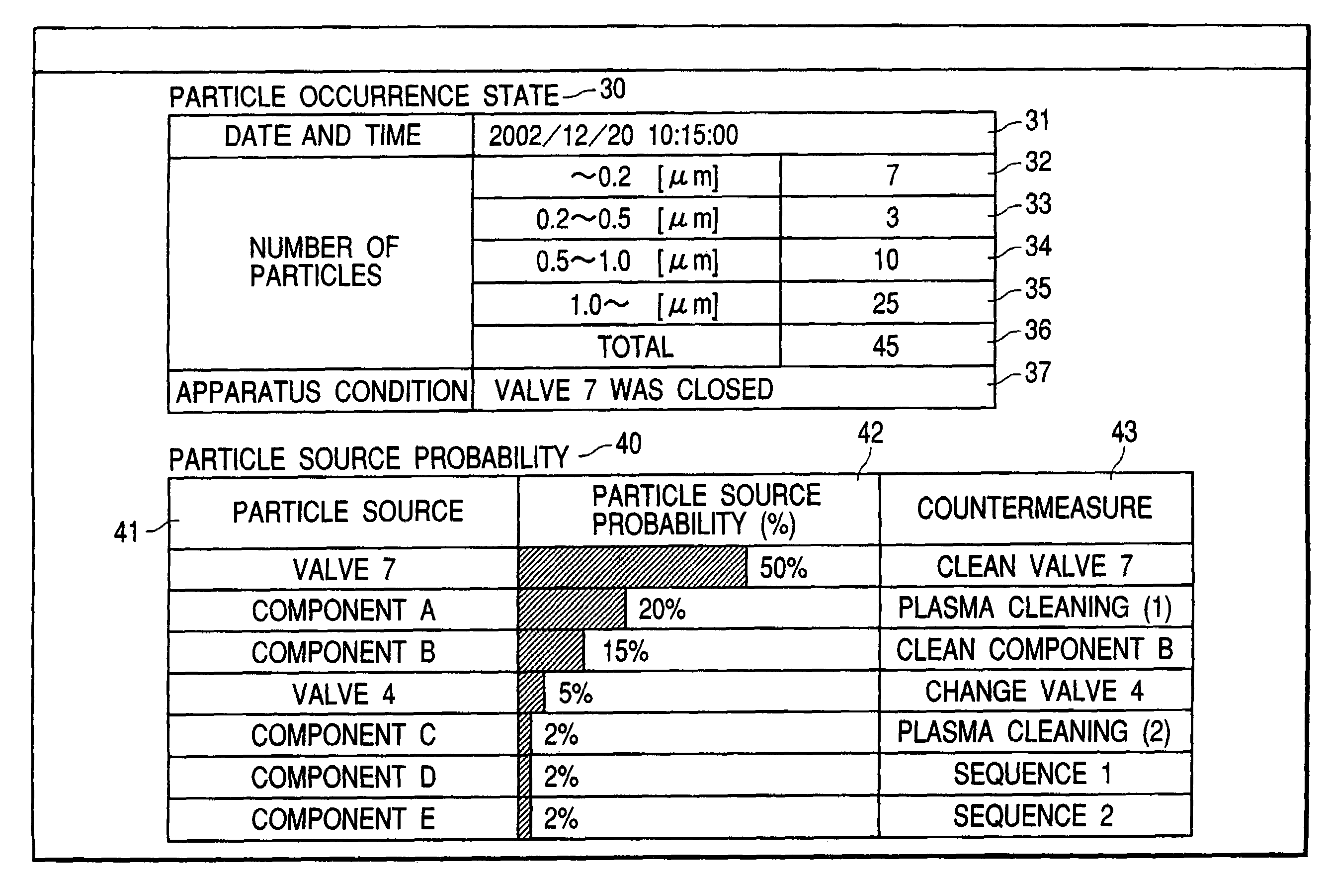
[0025]A particle measurement window 4 is provided on a wall of the vacuum reactor 2. A gas delivery unit 5 supplies processing gases to the vacuum reactor 2. A particle monitor 6 emits laser light to the interior of the vacuum reactor 2 through the window 4 and detects laser light which is scattered by the particles in the vacuum reactor 2, to thereby detect the size (particle size) of floating particles and the number of particles present in the vacuum reactor 2. The detected values are outputted as particle data.

[0026]A gas exhaust unit 8 exhausts the gases from the vacuum reactor 2 to maintain a gas pressure in the v...

third embodiment

[0046]FIG. 7 is a diagram illustrating the present invention. In FIG. 7, vacuum processing apparatuses 100a, 100b and 100c are controlled by a data managing unit 200. In the present embodiment, the data managing unit 200 is a portable unit. In actual use, the operator carries the data managing unit 200 to a location where the vacuum processing apparatuses 100a, 100b and 100c, which should undergo particle control, are installed, and the operator attaches it selectively to any one of the vacuum processing apparatuses 100a, 100b and 100c, as shown in dashed line in FIG. 7.

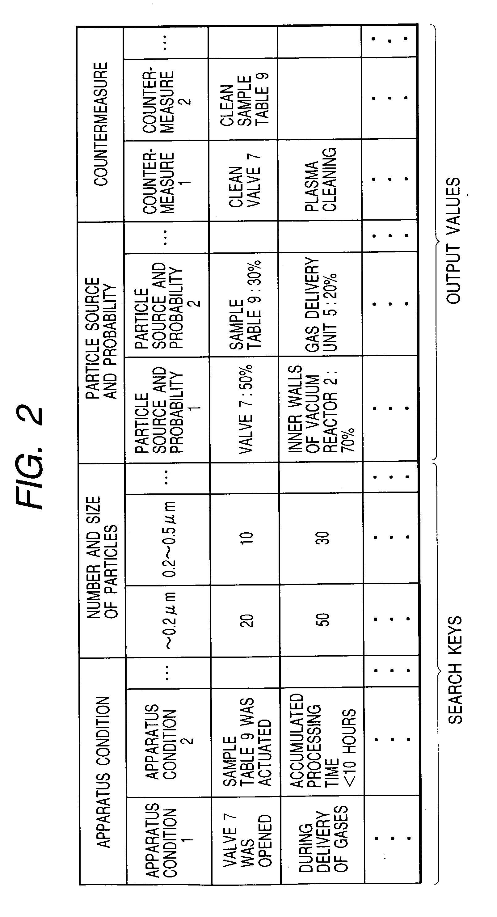
[0047]In this case, too, the data managing unit 200 searches a particle source database 20, using a search key that is generated on the basis of the received combined data, to provide a search result. The particle source database 20 may preferably be provided with a section for each of the vacuum processing apparatuses 100a, 100b and 100c, so that the search and search result for each of the vacuum processing apparat...


PUM

PropertyMeasurementUnit
particle sizeaaaaaaaaaa

Abstract

A particle control device and a particle control method are capable of controlling the occurrences of particles in a vacuum reactor. The particle control device is used in a vacuum processing apparatus having a vacuum reactor, a gas delivery unit for supplying processing gases to the vacuum reactor, and a sample table for supporting a sample in the vacuum reactor, wherein the apparatus subjects the sample to vacuum processing. The particle control device detects particles floating inside the vacuum reactor; generates apparatus condition data indicating a condition of the vacuum processing apparatus; and determines a component which is high in a particle occurrence probability based on detected particle data and apparatus condition data, thereby enabling display of the component selected as the particle source.

Description

BACKGROUND OF THE INVENTION[0001]The present invention relates to a particle control device and a particle control method for use in a vacuum processing apparatus; and, more particularly, the invention relates to a particle control device and a particle control method for a vacuum processing apparatus that is capable of monitoring and controlling the occurrence of particles in a vacuum processing apparatus.[0002]A vacuum processing apparatus, such as a plasma etching apparatus, generates plasma in a vacuum reactor in a state where the vacuum reactor is charged with etching gases. A predetermined semiconductor circuit is formed by causing radicals and ions, that are generated in the plasma, to react with a wafer surface to be etched. In such a plasma etching apparatus, reaction products, which are generated in the etching process, are deposited on the inner walls and electrodes of the vacuum reactor. The deposited reaction products tend to strip off from the inner walls and the elect...

Claims


Application Information

Patent Timeline
Patent Type & Authority Patents(United States)
IPC IPC(8): H01L21/00C23C14/00C23C16/44C23F4/00H01J37/32H01L21/3065
CPCH01J37/32431H01L21/67253H01J2237/0225
Inventor SHIRAISHI, DAISUKEKAGOSHIMA, AKIRAYAMAMOTO, HIDEYUKIARAI, TAKESHINAKANO, HIROYUKI
Owner HITACHI HIGH-TECH CORP
Why Eureka
Try Eureka