Voltage buffer for capacitive loads

a voltage buffer and capacitive load technology, applied in the field of voltage buffers, can solve the problem that reference voltage cannot drive the load sufficiently, and achieve the effect of stabilizing the loop, reducing the quiescent current of the buffer, and improving the settling tim

Inactive Publication Date: 2007-01-23
SANDISK TECH LLC
View PDF29 Cites 7 Cited by
  • Summary
  • Abstract
  • Description
  • Claims
  • Application Information

AI Technical Summary

Benefits of technology

[0010]In a principle aspect of the present invention, by removing the load from the feedback loop, the loop is stabilized. In another aspect of the present invention, this stabilization is achieved without the need of a compensating capacitor or with a much smaller compensating capacitor than in the prior art, allowing the quiescent current of the buffer to be reduced and the settling time to be improved. One preferred use of the present invention is to drive the data storage elements of a non-volatile memory.

Problems solved by technology

A driver of this kind is used when it is wanted to apply a reference voltage, Vin, to a load, but the source of the reference voltage cannot drive the load sufficiently.

Method used


Image

  • Voltage buffer for capacitive loads
  • Voltage buffer for capacitive loads
  • Voltage buffer for capacitive loads

Examples


Embodiment Construction

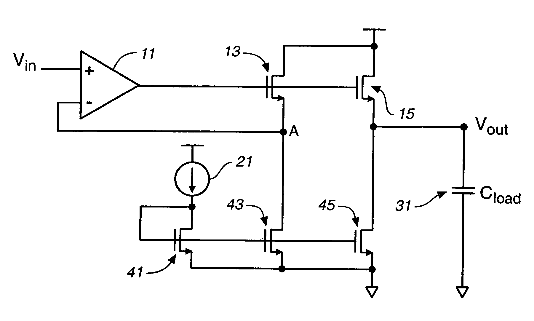
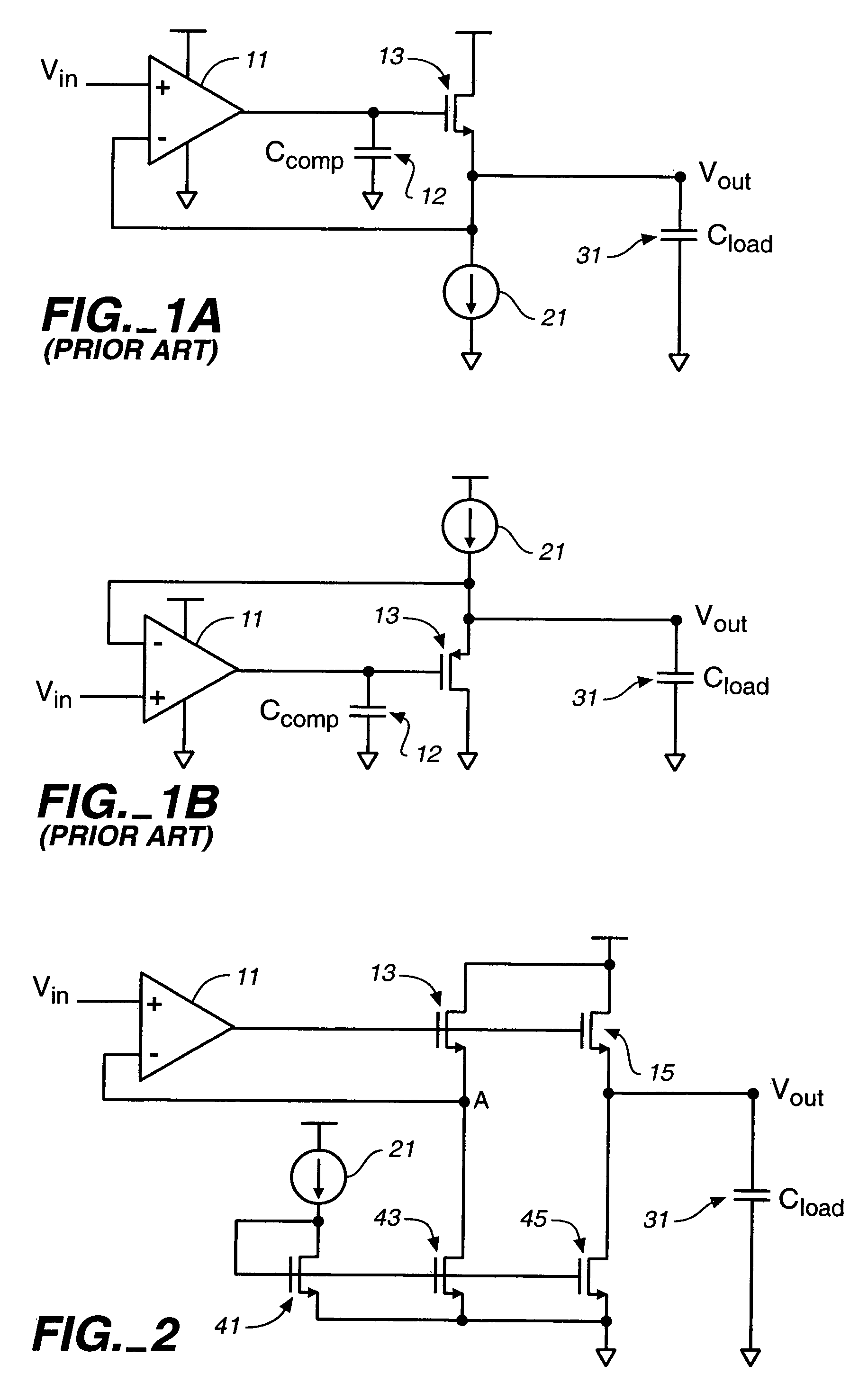
[0016]A first exemplary embodiment of the present invention is shown in FIG. 2. As is described in the following, this provides a unity gain buffer able to drive analog voltages on large and potentially variable capacitive loads with small quiescent current and fast settling times. In particular, in the design of FIG. 2, although the reference voltage Vin still determines the level on the node Vout connected to the load Cload 31, this node has been isolated from the feedback loop to the differential gain stage 11. Although the design of FIG. 2 uses a variation of source follower output stage, this isolating of the load allows the feedback loop to be stabilized in the presence of large loads without having to add large compensation capacitors, such as Ccomp 12 in FIGS. 1a and 1b, to introduce a dominant pole in the loop.

[0017]FIG. 2 again shows a reference voltage Vin applied to a first input of differential gain stage or op-amp 11, whose output is connected to the control gate of a ...


PUM


Abstract

A voltage buffer for capacitive loads isolates the load from the feedback loop. Using a variation of a follower arrangement, a second transistor outside of the feedback loop introduced. The current to the load is supplied through the second transistor, which is connected to have the same control gate level as the transistor in the feedback loop and provide an output voltage based on the reference input voltage. The output voltage is dependent upon the input voltage, but the load is removed from the feedback loop. By removing the load from the feedback loop, the loop is stabilized with only a very small or no compensating capacitor, allowing the quiescent current of the buffer to be reduced and the settling time to be improved. One preferred use of the present invention is to drive the data storage elements of a non-volatile memory.

Description

CROSS-REERENCE TO RELATED APPLICATION[0001]This application is a continuation of application Ser. No. 10 / 356,098, filed on Jan. 30, 2003, now U.S. Pat. No. 7,002,401 B2, which is hereby incorporated by this reference.BACKGROUND OF THE INVENTION[0002]This invention pertains to voltage buffers to drive analog voltages, and, in particular, relates voltage buffers for large and potentially variable capacitive loads.[0003]A conventional driving circuit or driver for a capacitive load typically consists of a signal input, a signal output, and an amplifier of an analog voltage buffer to drive the load. A common example of such a circuit is shown in FIG. 1a. A driver of this kind is used when it is wanted to apply a reference voltage, Vin, to a load, but the source of the reference voltage cannot drive the load sufficiently. This particular example uses an amplifier with a source follower output stage. Other examples include using am amplifier with a class A or a class A / B output stage. In ...

Claims


Application Information

Patent Timeline
Patent Type & Authority Patents(United States)
IPC IPC(8): G05F1/10H03F3/45H03F3/50
CPCG11C27/005G11C27/028H03F1/342H03F3/45475H03F3/505H03F2203/5027H03F2200/366H03F2200/453H03F2200/78H03F2203/5021H03F2200/297H03F3/45H03F3/50H03K19/0175
Inventor KHALID, SHAHZAD
Owner SANDISK TECH LLC
Why Eureka
Try Eureka