Method for navigating in the interior of the body using three-dimensionally visualized structures

a three-dimensional visualization and interior technology, applied in the field of interior navigation using three-dimensional visualization structures, can solve the problems of difficult surgery for surgeons, often even impossible to optically survey the anatomical structure of patients, and insufficient two-dimensional images such as x-ray images, and achieve the effect of facilitating the alignment of the effective axis

Active Publication Date: 2007-01-23
STRYKER EURO OPERATIONS HLDG LLC
View PDF17 Cites 205 Cited by
  • Summary
  • Abstract
  • Description
  • Claims
  • Application Information

AI Technical Summary

Benefits of technology

[0028]In accordance with a further embodiment of the invention, a navigation aid may be formed for the instrument in the above-described graphical representation of the geometrical structure to be visualized or in a separate representation. The navigation aid indicates for example, the actual position of the effective axis of the surgical instrument relative to a preferred direction to be visualized in the form of a tunnel structure. The navigation aid may comprise, furthermore, directional arrows that facilitate the alignment of the effective axis along the preferred direction.

Problems solved by technology

For this reason, it is difficult for the surgeon and often even impossible to survey optically those anatomical structures of the patient that are relevant to the operation.
Both for the precise planning of an operation and for the optical monitoring of the course of the operation, two-dimensional images, such as X-ray images, are as a rule inadequate.
Because of the equipment factors and because of the high computational expenditure, CT methods are primarily used to obtain preoperative data.
CT methods are therefore unsuitable for an intraoperative visualization, i.e. a visualization taking place during the operation.
Furthermore, the high radiation exposure accompanying the CT methods is in many cases undesirable for the patient.

Method used


Image

  • Method for navigating in the interior of the body using three-dimensionally visualized structures
  • Method for navigating in the interior of the body using three-dimensionally visualized structures
  • Method for navigating in the interior of the body using three-dimensionally visualized structures

Examples


Embodiment Construction

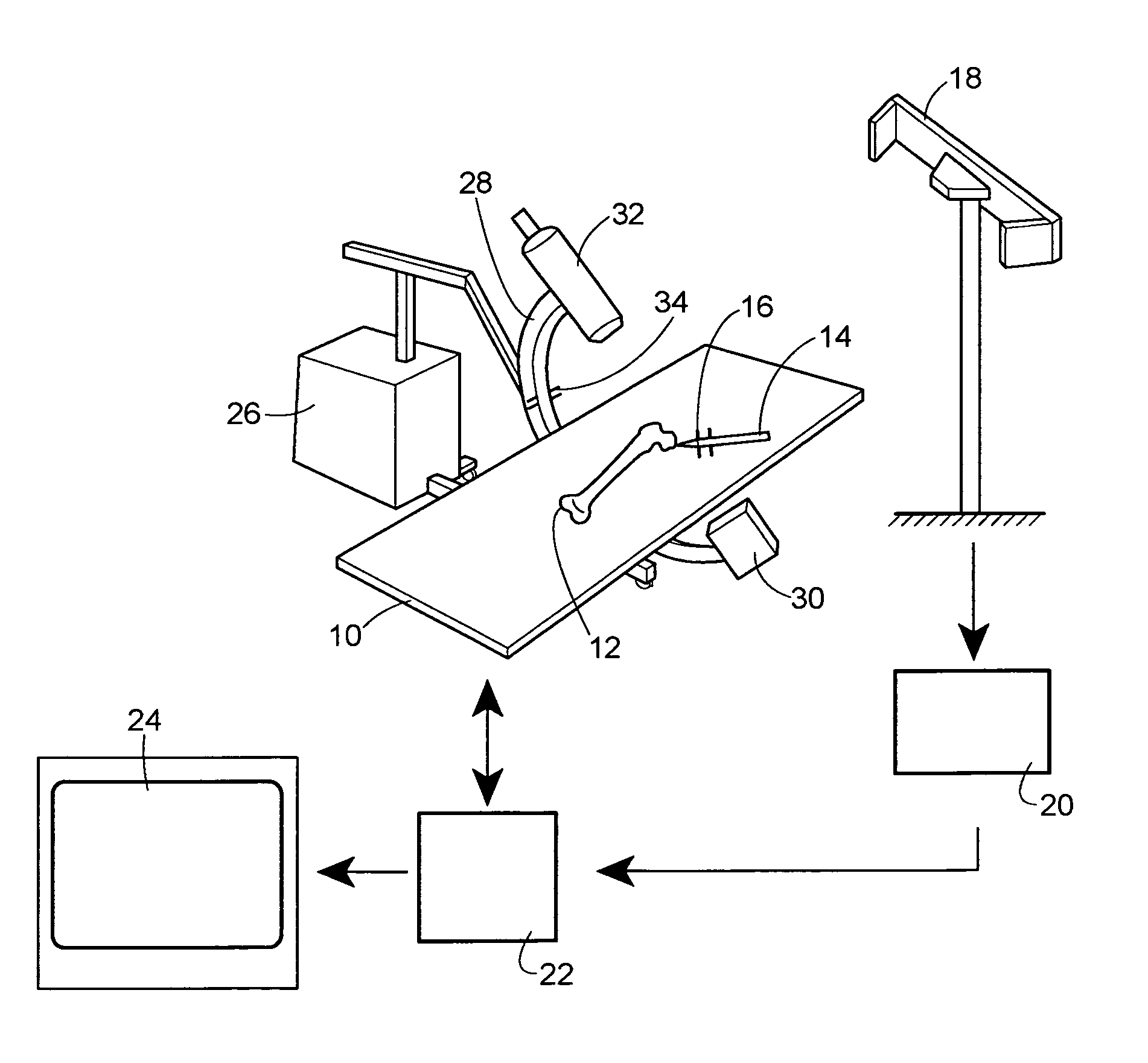
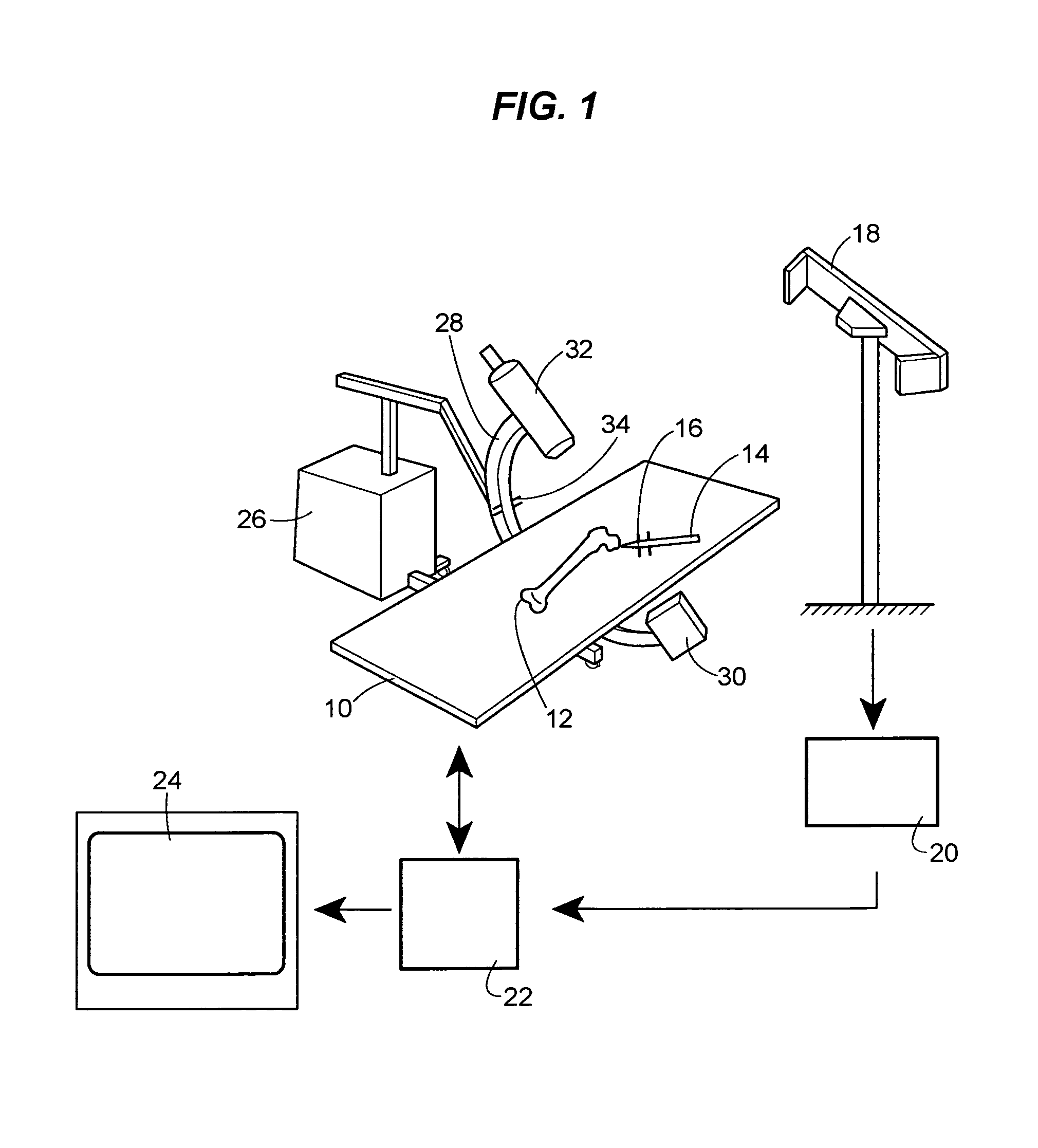
[0040]FIG. 1 shows diagrammatically an operation scenario based on the visualization method according to the invention. Disposed on an operating table 10 is an anatomical object to be treated operatively in the form of a femur bone 12. The surgical intervention is performed with the aid of a surgical instrument 14. Attached to the surgical instrument 14 is a marker 16 of an infrared tracking system. Said marker 16 is designed to transmit infrared radiation. The infrared tracking system comprises, furthermore, an infrared detector 18 disposed in a positionally fixed manner. A localization computer 20 of the tracking system calculates the actual spatial position of the surgical instrument 14 provided with the marker 16 from the signals received by the infrared detector 18. The calculated spatial co-ordinates are transmitted by the localization computer 20 via a data bus to a central computer 22, where they are processed graphically and represented graphically on a viewing screen 24.

[0...


PUM


Abstract

A method is described for navigating in the interior of the body using three-dimensionally visualized structures. In a first step of the method, at least two two-dimensional images of the same anatomical object are provided from different perspectives, and also items of information that make it possible to draw conclusions about the respective spatial position of an imaging system relative to the anatomical object. The projections of a geometrical structure to be visualized are then created in every two-dimensional image, wherein a geometrical structure to be visualized is created in each two-dimensional image, wherein the geometrical structure to be visualized is different from the anatomical object. A cone surface is then generated in space for each image wherein the spatial positions of the cone vertex and cone directrix are determined from the respective spatial position of the imaging system and the shape of the cone directrix is determined from the shape of the projection of the geometrical structure to be visualized on the image. Finally, a spatial intersection of the individual cone surfaces is formed to determine the geometrical structure and the geometrical structure determined and/or an intersection of a plurality of geometrical structures determined are/is represented and the representation is used for navigation.

Description

[0001]This application is a 371 pf PCT / EP01 / 08844 filed Jul. 31, 2001.BACKGROUND OF THE INVENTION[0002]The invention relates to a method for navigating, for example a surgical instrument or an endoscope, in the interior of the body using three-dimensionally visualized structures.[0003]During surgical operations, an attempt is made, as a rule, to make as small a cut as possible through the skin of the patient. Said cut is often just big enough in order to be able to reach the anatomical structure to be treated in the interior of the body with surgical instruments. For this reason, it is difficult for the surgeon and often even impossible to survey optically those anatomical structures of the patient that are relevant to the operation. Even the position, for example, of surgical instruments relative to an anatomical object to be treated is often not visible to the surgeon. For this reason, methods of visualizing structures in the interior of the body for the purpose of navigating such...

Claims


Application Information

Patent Timeline
Patent Type & Authority Patents(United States)
IPC IPC(8): A61B5/05G06K9/00A61B34/10A61B34/20A61B90/00G06T15/20
CPCA61B19/5244G06T7/0067G06T7/0075G06T15/20G06T19/003A61B19/52A61B19/50G06T2210/41A61B19/56A61B2019/505A61B2019/507A61B2019/5255A61B2019/5268A61B2019/5289A61B2019/5295G06T2207/10088G06T2207/10112G06T2207/30008A61B90/36A61B2034/2055A61B2034/2068A61B2090/367A61B34/20A61B34/25A61B2090/364A61B34/10A61B2034/105A61B2034/107G06T7/564G06T7/593
Inventor SCHWEIKARD, ACHIMDOETTER, MANFREDROTH, MICHAELDE LA BARRERA, JOSE-LUIS MOCTEZUMA
Owner STRYKER EURO OPERATIONS HLDG LLC
Why Eureka
Try Eureka