Measuring method in magnetic resonance imaging device and magnetic resonance imaging device

a magnetic resonance imaging and measuring method technology, applied in the field of magnetic resonance imaging apparatuses, can solve the problems of deteriorating image quality, affecting the quality of image produced in the high frequency region, and affecting the accuracy of measurement results, so as to improve the quality of reproduction images, reduce the degree of dependency on the direction appearing in the measurement result, and improve the effect of temporal resolution

Inactive Publication Date: 2007-01-23
HITACHI MEDICAL CORP
View PDF7 Cites 8 Cited by
  • Summary
  • Abstract
  • Description
  • Claims
  • Application Information

AI Technical Summary

Benefits of technology

[0019]It is an object of the present invention to realize a measuring method and apparatus which are capable of reducing a measuring time in each session, and eliminating the direction dependency from the result of measurement without significantly deteriorating the temporal resolution in a high frequency range when imaging is repeatedly performed in MRI.
[0050]Further, according to such a measuring method and apparatus, the measuring space is a three-dimensional space, and a boundary line between the essential measurement region and the respective divided (peripheral) measurement regions in the entire three-dimensional measuring space is a line which divides the entire three-dimensional measuring space in at least two dimensional coordinate axis directions of three-dimensional coordinate axes which define the measuring space. Thus, as compared with U.S. Pat. Nos. 5,713,358 and 5,830,143 in which the measuring space is divided only in the ky-direction, degree of dependency on the direction appearing in the measurement result can be reduced and also the degradation in the quality of a reproduced image can be reduced.
[0051]Further, the entire region of the measuring space is not measured but a spatial frequency portion which is not important in the measurement object is set as a non-measurement region, temporal resolution can be improved without largely degrading the matching degree to the measuring object.

Problems solved by technology

However, the techniques described in the aforementioned U.S. Pat. Nos. 5,713,358 and 5,830,143 experience a significantly large degradation in the temporal resolution in a high frequency region.
Also, since the k-space is divided only in a one-dimensional direction, i.e., the ky-direction, the result of measurement depends on the direction, causing a deteriorated quality of an image produced therefrom.

Method used


Image

  • Measuring method in magnetic resonance imaging device and magnetic resonance imaging device
  • Measuring method in magnetic resonance imaging device and magnetic resonance imaging device
  • Measuring method in magnetic resonance imaging device and magnetic resonance imaging device

Examples


first embodiment

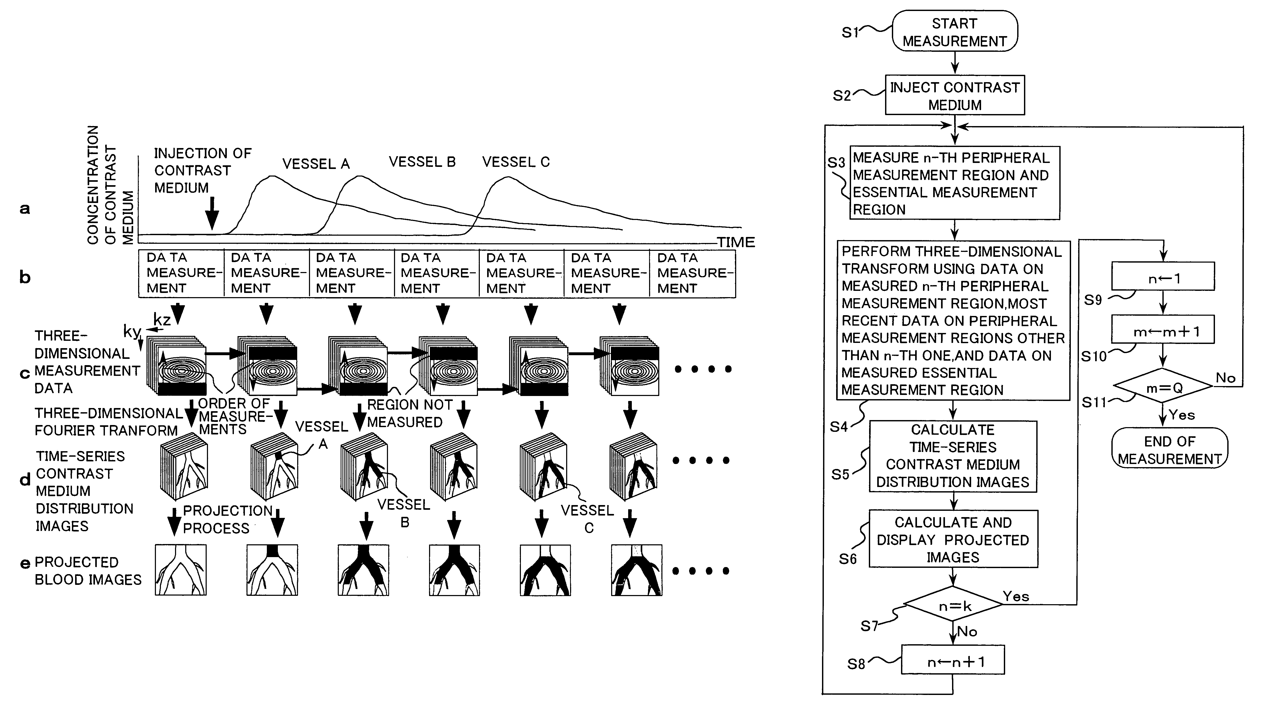
[0092]In contrast, the present invention does not fix the numbers of steps and step widths in the Z- and Y-directions in each session of measurement in the dynamic MRA imaging, and controls each session of measurement in the following manner.

[0093]Specifically, in the first embodiment of the present invention, an essential measurement region which is a central region, and a plurality of peripheral measurement regions (divided measurement regions) around the essential measurement region are set on a two-dimensional k-space which has coordinate axes ky, kz, the magnitudes of which have been previously determined in accordance with the numbers of possible phase encoding steps in the Z- and Y-directions.

[0094]Here, each of the peripheral measurement regions may partially include the same region as other peripheral measurement regions. The essential measurement region is measured without fail in each session of measurement, while the respective peripheral measurement regions are measured...

second embodiment

[0157]Next, description will be made on the present invention.

[0158]According to the second embodiment, on the ky-kz plane of the three-dimensional k-space having kx, ky and kz coordinate axes which sizes are determined according to the numbers of frequency encoding in the x-direction and the numbers of encoding steps in the Z- and Y-directions, an essential measurement region is set as a center region centered around the origin and a peripheral measurement region is set around the essential measurement region. For the peripheral measurement region, all the sampling points existing within the peripheral measurement region are divided into plural groups.

[0159]Although this is the same as the first embodiment, the second embodiment differs from the first embodiment in a manner that the peripheral measurement region is divided not into plural regions but into plural groups such that the sampling points in each of the groups are distributed so as not to be clustered spatially from one a...

third embodiment

[0187]Next, description will be made on the present invention.

[0188]According to the third embodiment, as an example, a peripheral measurement region is further divided in to a low and intermediate frequency region and a high frequency region and sampling points within each of these regions are divided into groups within each of which the sampling points are distributed uniformly in space.

[0189]That is, as illustrated in FIG. 18, the k-space is divided into an essential measurement region 61 of a low frequency region containing the origin, a low and intermediate frequency region 62 provided at the outside of the essential measurement region and a high frequency region 63 provided at the outside of the low and intermediate frequency region. The respective regions 61, 62 and 63 are mutually exclusive regions and so do not overlap from one another.

[0190]The essential measurement region 61 is a region to be measured at each session of measurement, like the second embodiment. Each of the...


PUM


Abstract

In a measuring space of the object (1), an essential measurement region (41, 61, 71, 81, 111, 131) having a center region of the measuring space and a plurality of peripheral measurement regions (42, 62, 63, 72, 82, 112, 132) which do not have any region overlapped with the essential measurement region are set. Then, the essential measurement region is combined with a selected peripheral portion of the plurality of the peripheral measurement regions to measure in a preceding manner a nuclear magnetic resonance signal from the object as data of the measuring space. The essential measurement region is combined with the peripheral measurement region of the plurality of the peripheral measurement regions which has not been selected in the preceding measuring step to measure a nuclear magnetic resonance signal from the object as data of the measuring space. Sequentially, the essential measurement region is combined with the peripheral measurement region having not been measured in a preceding measuring step to measure a nuclear magnetic resonance signal from the object. The data of the essential measurement region and the data of the peripheral measurement region thus measured is supplemented with the data of the peripheral measurement region measured in the preceding measuring step to generate data of the measuring space.

Description

TECHNICAL FIELD[0001]The present invention relates to a magnetic resonance imaging (MRI) apparatus which utilizes a nuclear magnetic resonance phenomenon to produce a tomographic image of an object to be examined, and more particularly, to a measuring method and apparatus suitable for dynamic magnetic resonance angiography imaging in a magnetic resonance imaging apparatus.BACKGROUND ART[0002]The MRI (magnetic resonance imaging) apparatus utilizes the NMR phenomenon to measure a density distribution, a relaxation time distribution, and the like of nuclear spins in a desired portion under testing of the object, and displays an image of a cross-section of an arbitrary portion of the object from the measured data.[0003]The technology for producing a blood flow image utilizing such a magnetic resonance imaging apparatus is called MRA (magnetic resonance angiography). This MRA can be roughly classified into an approach which uses a contrast medium and an approach which does not use the co...

Claims


Application Information

Patent Timeline
Patent Type & Authority Patents(United States)
IPC IPC(8): A61B5/05A61B5/055G01R33/54G01R33/563
CPCA61B5/055G01R33/563G01R33/4833A61B5/7257
Inventor ABE, TAKAYUKIWATANABE, SHIGERUTAKESHIMA, HIROTAKA
Owner HITACHI MEDICAL CORP
Why Eureka
Try Eureka