System and device for detecting yaw displacements using stand-by measuring channels

a technology of yaw displacement and detection system, applied in the direction of braking system, vehicle position/course/altitude control, instruments, etc., can solve the problems of limited yaw movement, dangerous situations, undesirable control actions,

Inactive Publication Date: 2007-01-23
CONTINENTAL TEVES AG & CO OHG
View PDF13 Cites 42 Cited by
  • Summary
  • Abstract
  • Description
  • Claims
  • Application Information

AI Technical Summary

Benefits of technology

[0035]According to a favorable embodiment of the present invention, the yaw rate sensors are accommodated in an internal housin...

Problems solved by technology

If the actual value of the yaw movement differs from the calculated nominal value by a predetermined amount jeopardizing driving stability, the yaw movement is limited to allowable values by a specified brake and engine intervention.
This demands a high degree of functional safety from the sensors because their malfunctions may effect, under certain circumstances, braking actions or a neutralization of braking effects at a wrong point of time, thereby potentially triggering dangerous situations.
This is especially applicable to a yaw rate sensor in which a moderate exceeding of allowable drift tolerances for accuracy and precision may cause undesirable control actions.
However,...

Method used


Image

  • System and device for detecting yaw displacements using stand-by measuring channels
  • System and device for detecting yaw displacements using stand-by measuring channels
  • System and device for detecting yaw displacements using stand-by measuring channels

Examples


Embodiment Construction

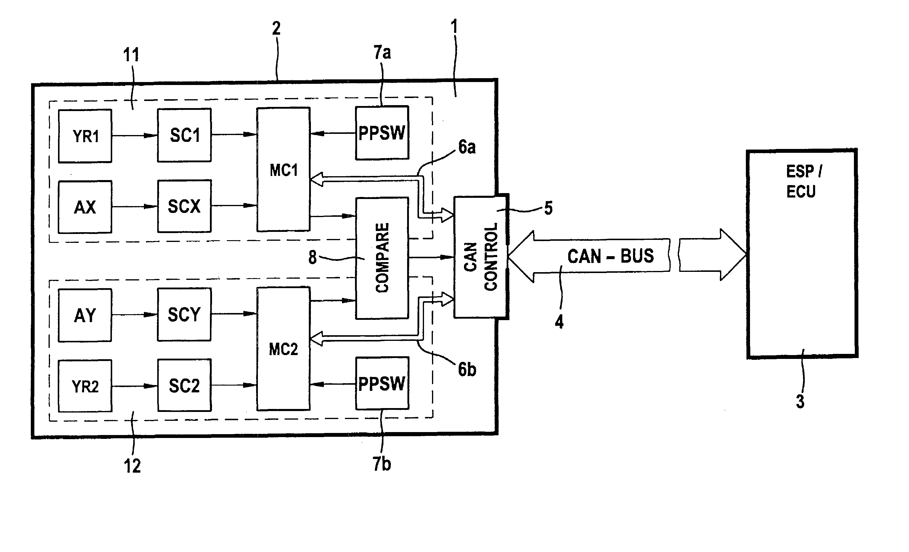
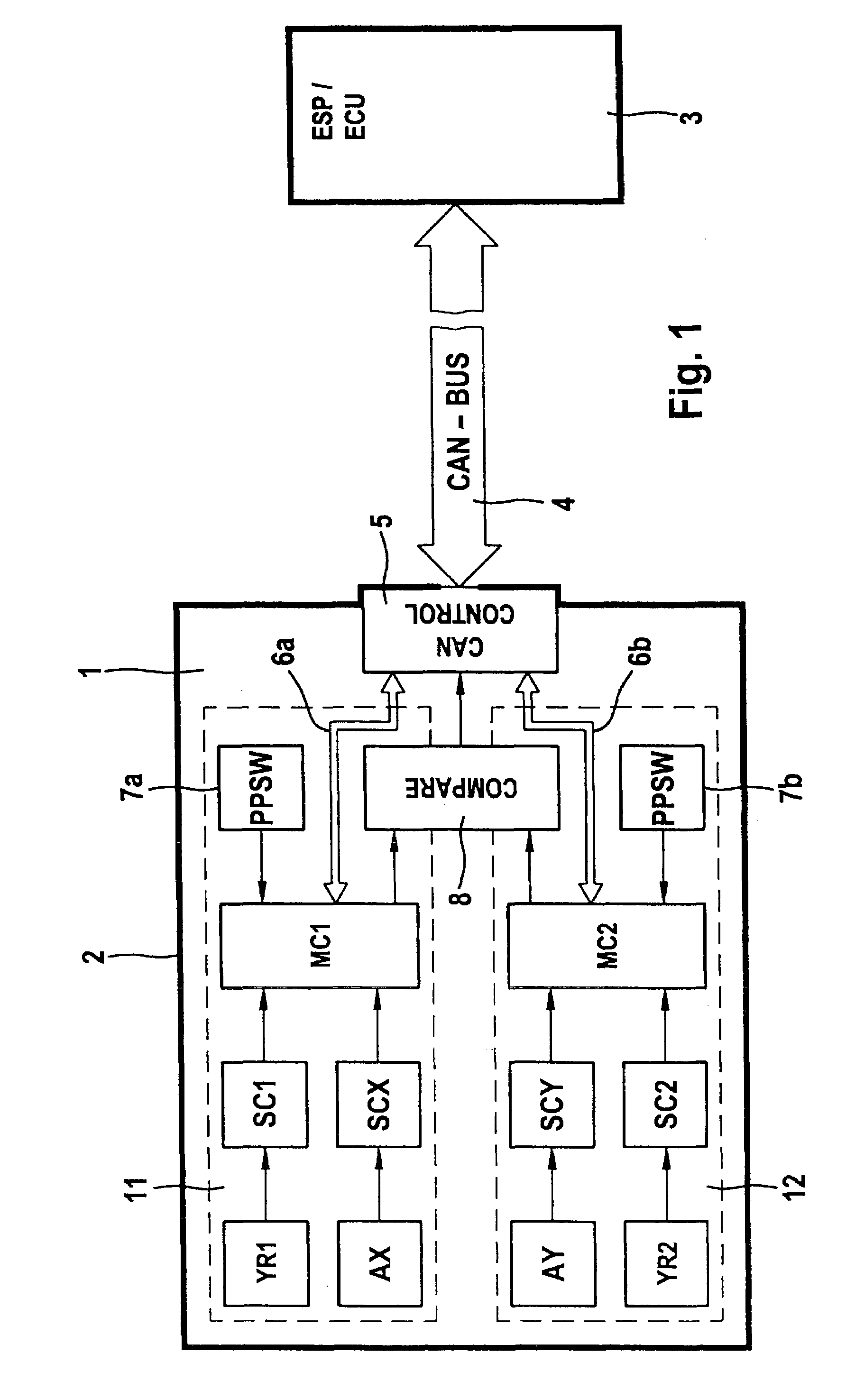
[0041]FIG. 1 shows a schematic view of the technical interaction of the components of a system of the type according to the present invention. The system is configured as a device 1 for the simultaneous acquisition of yaw rate, longitudinal acceleration, and transverse acceleration for ESP applications. The device has a housing 2 inside which all components are accommodated. There is a CAN-bus connection 4 between the device and the electronic controller of the ESP system 3. The CAN-bus controller 5 is a component part of the device. The system structurally comprises two independent measuring channels 11, 12. These measuring channels are in general similar sensor branches. The first measuring channel 11 is comprised of the yaw rate sensor YR1 with an associated signal conditioning circuit SC1 and the longitudinal acceleration sensor AX with an associated signal conditioning circuit SCX. The signals of these sensors are front-end processed in terms of signal technology in a first mic...


PUM


Abstract

The present invention relates to a system for detecting safety-critical measured quantities, in particular yaw rates or acceleration data in automotive vehicles, comprising at least two independent measuring channels with sensors that are independent of one another and elements for verifying a malfunction or a failure of the measuring channels. The first measuring channel and the additional measuring channel(s) are operated in hot redundancy employing sensors of the similar type but not exactly identical in such a manner that the sensors are operated in parallel and without restriction. This invention also relates to a device consisting of a sealed housing with a plug, and the aforementioned system is accommodated in the sealed housing.

Description

TECHNICAL FIELD[0001]The present invention generally relates to yaw angle detection systems and more particularly relates to a method and apparatus for improving the robustness of a yaw angle detection system.BACKGROUND OF THE INVENTION[0002]Driving stability control systems (ESP) for governing and limiting undesirable yaw movements about the vertical axis are known in the art. Essential quantities that can be varied deliberately by the driver are measured by means of sensors whereby to calculate a nominal yaw rate. The quantities refer to the steering angle, the accelerator pedal position, the braking pressure, the transverse acceleration, and the rotational behavior of the individual vehicle wheels. In addition, the actual value of the yaw rate developing as a reaction to the driving maneuver is measured using a yaw rate sensor. If the actual value of the yaw movement differs from the calculated nominal value by a predetermined amount jeopardizing driving stability, the yaw moveme...

Claims


Application Information

Patent Timeline
IPC IPC(8): G06F19/00B60T8/00B60T8/17B60T8/171B60T8/36B60T8/88
CPCB60T8/171B60T8/885B60T8/3675B60T2270/413
Inventor LOHBERG, PETERBURGHARDT, ROLANDZYDEK, MICHAEL
Owner CONTINENTAL TEVES AG & CO OHG
Why Eureka
Try Eureka