Ultra lightweight, high efficiency bicycle suspension

a bicycle suspension, ultra-light weight technology, applied in the direction of bicycle springs, foldable cycles, cycle equipment, etc., can solve the problems of fatiguing and dangerous riders, loss of control of the bike, race damage to riders and their equipment, etc., to achieve the effect of adding weight to the bike, weight and complexity

Active Publication Date: 2007-01-30
TREK BICYCLE CORPORATION
View PDF19 Cites 26 Cited by
  • Summary
  • Abstract
  • Description
  • Claims
  • Application Information

AI Technical Summary

Benefits of technology

[0009]Some road racing teams have used front suspension forks on these rougher courses. These forks are typically add at least 1 kilogram of mass to the bike. This is a large amount of weight to add and a considerable detriment to the bikes performance on a moderate to smooth road. As they have a significant amount of stiction, the static friction resulting from the sliding seals and bearings which must be overcome before the suspension can begin to move, they are only partially effective at attenuating the front wheel shocks. They provide noticeable cushioning of the hands of the rider, but not much for the saddle or feet, where most of the riders weight is. Most of the weight of the cyclist, and the all of the cyclists forward driving force is located at the rear wheel. So suspension and better traction is likely to be at least, if not more useful on the rear than on the front wheel. In addition, the sliding type front forks have a tendency to move up and down with each pedal stroke, unless the stiction is high enough to prevent it. This motion wastes the rider's energy. But higher stiction reduces the amount of road shock that the front fork attenuates.
[0011]The invention is intended to attenuate the amplitude of deflections that the rider feels, both in the feet and seat. This will reduce fatigue in the rider, especially over a longer course. The invention is further intended to improve the adhesion of the tires to the pavement, by reducing the amount of time they are not in contact with the road surface and reducing the variation or amplitude of forces between the tire and the ground.
[0015]Some of the prior art suspension designs used curved seatstays. The bend(s) destabilize the seat stay tubes, and cause it to flex more when an axial load is applied, either by the riders weight or by a momentary bump impact. Unfortunately, the bends also greatly reduce the capability of a given tube to support an axial load. Thus, the bent seat stays must be made heavier than normal to provide adequate frame structure. One design uses a single large radius bend in the seatstays, but the amount of flex under compression is limited by a layer of polymer and a stainless steel strap under tension. This of course adds considerable weight to the overall structure, while providing less benefit than the current invention.
[0018]Adding pivots or reinforcing and substantially reshaping the chainstays, or adding flat springs to the chainstays all typically add weight to the bike. And since the resultant structure is not very rigid vertically, in order to take a large deflection in one direction for many cycles without fatigue, the compressive spring must be designed to take most of the compressive loads, making it heavier. There also needs to be a negative spring and mechanism for activating it included in these designs, which again adds weight and complexity.BRIEF DESCRIPTION OF THE DRAWINGS

Problems solved by technology

These can be extremely fatiguing and dangerous to the riders, causing many instances of loss of control of the bike and resultant crashes.
These races can be very damaging to the riders and their equipment.
The drawback is that additional mass on the bike degrades its performance in several ways and the larger tires typically add additional weight to the bike.
They do not have adequate reach adjustment or tire clearance to fit larger road tires.
So even if you designed more tire clearance into a frame, it would not be able to use this type of brake.

Method used


Image

  • Ultra lightweight, high efficiency bicycle suspension
  • Ultra lightweight, high efficiency bicycle suspension
  • Ultra lightweight, high efficiency bicycle suspension

Examples


Embodiment Construction

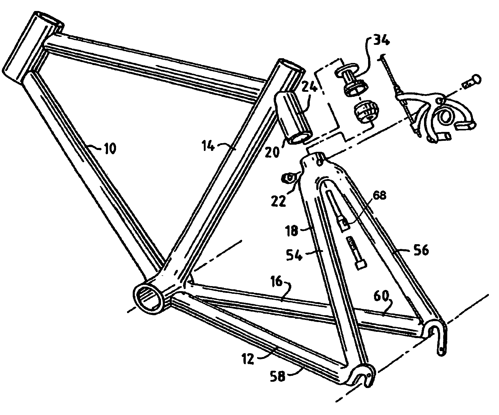
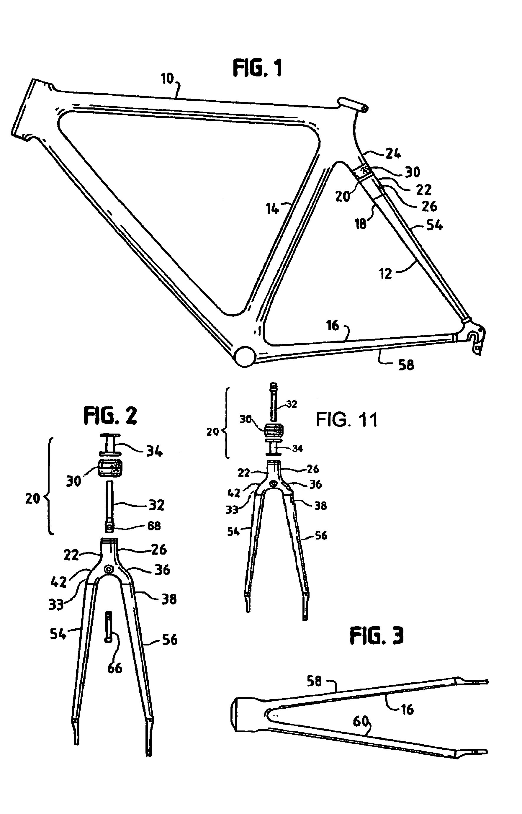
[0030]A bicycle frame 10 of the well known diamond configuration has head tube, down tube, top tube, and a rear triangle 12 generally made up of a seat tube 14, a chainstay assembly 16 and a seatstay assembly 18. A shock absorber assembly 20 operates in conjunction with the other elements of the rear triangle 12 to provide an ultra lightweight, high efficiency bicycle suspension. The shock absorber assembly is generally identified by reference number 20, while its components are separately described below.

[0031]The invention is adaptable to various tubular section chainstay assemblies. Thus, in an aluminum frame, the lateral width of a cross section of the chainstays is approximately equal to or slightly greater than the vertical height of a cross section of the chainstays. While in a carbon fiber reinforced plastic frame, the height appears to be significantly greater than the width.

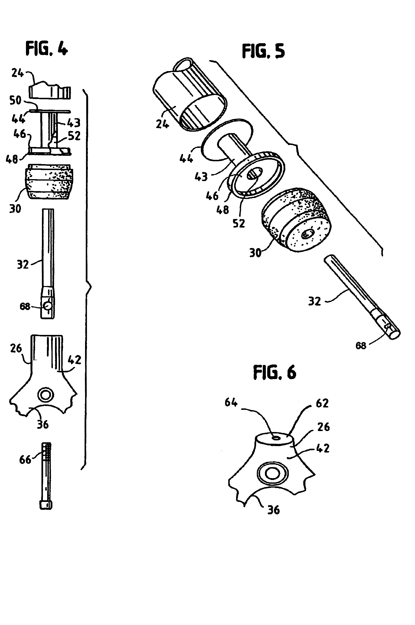
[0032]The shock absorber assembly 20 is incorporated into the wishbone 22 of the seat stay assembly ...


PUM


Abstract

A rear suspension road bicycle frame uses an integrated rear shock absorbing assembly installed in a typical diamond bicycle frame with a head tube, down tube, top tube, seat tube, tubular chainstays, tubular seat stays, brake bridge at the top of the seat stays connecting them, the shock absorbing assembly having an elastomer shock absorbing spring member with a slide affixed to the brake bridge, and a sliding bearing in the upper wishbone so that the preloaded spring member absorbs shock and the frame absorbs flexing tending to unload the spring member.

Description

BACKGROUND OF THE INVENTION[0001]1. Field of the Invention[0002]The invention is a rear suspension design which can be incorporated into light weight racing frames such as are used by professional racing teams.[0003]2. Summary of the Invention[0004]Professional racing teams race some extremely rough courses including many sections paved with cobblestones. These can be extremely fatiguing and dangerous to the riders, causing many instances of loss of control of the bike and resultant crashes. For example, one race that is famous for the amount of rough surface conditions is the Paris-Roubaix.[0005]These races can be very damaging to the riders and their equipment. They will sometimes use larger diameter tires than on normal courses in order to provide a little more cushion and more resistance to flatting on the harsh bumps. The drawback is that additional mass on the bike degrades its performance in several ways and the larger tires typically add additional weight to the bike. In add...

Claims


Application Information

Patent Timeline
Patent Type & Authority Patents(United States)
IPC IPC(8): B62D3/02B62K25/04B62K25/28
CPCB62K25/04B62K25/28B62K2201/02
Inventor KLEIN, GARY
Owner TREK BICYCLE CORPORATION
Why Eureka
Try Eureka