Pump aggregate for a hydraulic vehicle braking system

a technology for hydraulic vehicles and aggregates, applied in the direction of positive displacement liquid engines, piston pumps, liquid fuel engines, etc., can solve the problems of large axial length of the pump unit, large installation space, complicated and expensive known pump units, etc., and achieves low cost, high bending, and greater rigidity of the hollow shaft

Inactive Publication Date: 2007-01-30
ROBERT BOSCH GMBH
View PDF31 Cites 51 Cited by
  • Summary
  • Abstract
  • Description
  • Claims
  • Application Information

AI Technical Summary

Benefits of technology

[0013]Another advantage of the invention is that a diameter of the bearing point of the rotor shaft, that is, a diameter of the pin inserted into the hollow shaft, is less than an outside diameter of the hollow shaft. The bearing point of small diameter makes a bearing of small diameter possible, and thus a small installation space in the radial direction in each bearing region. Despite the small diameter of the rotor shaft of the pump unit of the invention at the bearing point, the rotor shaft has high bending and torsional strength, because of its embodiment as a hollow shaft. For the same amount of material used, the rigidity of the hollow shaft is greater than that of a solid shaft.
[0014]Preferably, the pin is press-fitted into the hollow shaft and as a result joined to the hollow shaft in a manner fixed against relative rotation and axial motion.
[0015]A standardized pin may be used as the pin for the rotor shaft. Such pins can be obtained inexpensively as mass-produced goods. Standardized pins typically have a hard surface, with a reduced diameter tolerance and high surface quality, which makes it suitable as a running face for slidingly bearing the rotor shaft. The hard surface of a standardized pin is equally well suited as a running face on which roller bodies of a roller bearing without an inner ring, such as a needle bearing, can roll. A standardized pin is also suitable for pressing on an inner ring of a roller bearing. As the standardized pin, a hardened cylindrical pin can be considered in particular.
[0016]One embodiment of the invention provides for producing the hollow shaft as a reformed part, especially by cold forging, instead of cutting it apart from a pipe. The reforming, in particular cold forging, has the advantage that the hollow shaft can be produced quickly and inexpensively, preferably in a single operation. Metal-cutting machining is not needed. By means of the reforming, a densification and / or a hard surface can be achieved.
[0017]In one embodiment of the invention, the pin inserted into the hollow shaft is integral with an eccentric element for driving the pump pistons of the pump, embodied as a piston pump, of the pump unit of the invention. This embodiment of the invention has the advantage of simple, inexpensive production of the eccentric element; in particular, the eccentric element can be produced integrally with the pin, quickly and simply, preferably in a single operation, as a reformed part and in particular as a cold-forged part. This has the advantage of not requiring a separate eccentric element. Producing the eccentric element integrally with the pin as a reformed part, particularly by means of cold forging, has the advantages that have already been mentioned for producing the hollow shaft by reforming / cold forging, that is, simple, fast production in a single operation, and the compaction of the material because of the reforming. Except for grinding the circumferential surface of the eccentric element, no postmachining or metal-cutting machining of the eccentric element produced by reforming, including of the pin integral with it, is needed.
[0018]The pump unit of the invention is intended in particular for use in a brake system of a vehicle and is used to control the pressure in wheel brake cylinders. Depending on the type of brake system, the abbreviations ABS (for anti-lock brake system), TCS (traction control system), VDC (vehicle dynamics control) and EHB (electrohydraulic brake system) are used for such brake systems. In the brake system, the pump unit serves for instance to return brake fluid from a wheel brake cylinder or a plurality of wheel / brake cylinders to a master cylinder (ABS) and / or to pump brake fluid out of a supply container into a wheel brake cylinder or a plurality of wheel brake cylinders (TCS or VDC or EHB). The pump unit is needed in a brake system with wheel slip control (ABS or TCS) and / or a brake system serving as a steering aid (VDC) and / or an electrohydraulic brake system (EHB). With the wheel slip control (ABS or TCS), locking of the wheels of the vehicle during a braking event involving strong pressure on the brake pedal (ABS) and / or spinning of the driven wheels of the vehicle in the event of strong pressure on the gas pedal (TCS) can for instance be prevented. In a brake system serving as a steering aid (VDC), a brake pressure is built up in one or more wheel brake cylinders independently of an actuation of the brake pedal or gas pedal, for instance to prevent the vehicle from breaking out of the track desired by the driver. The pump unit can also be used in an electrohydraulic brake system (EHB), in which the pump unit pumps the brake fluid into the wheel brake cylinder or wheel brake cylinders if an electric brake pedal sensor detects an actuation of the brake pedal, or in which the pump unit is used to fill a reservoir of the brake system.

Problems solved by technology

The known pump unit has the disadvantage of being complicated and expensive to produce and manufacture.
Another disadvantage is that in the region of the pump pistons, two bearings are disposed one inside the other, namely the bearing in the eccentric bush and the bearing disposed on the outside of the eccentric bush, making a radially large installation space necessary.
As a result, a great axial length of the pump unit is necessary.

Method used


Image

  • Pump aggregate for a hydraulic vehicle braking system
  • Pump aggregate for a hydraulic vehicle braking system
  • Pump aggregate for a hydraulic vehicle braking system

Examples


Embodiment Construction

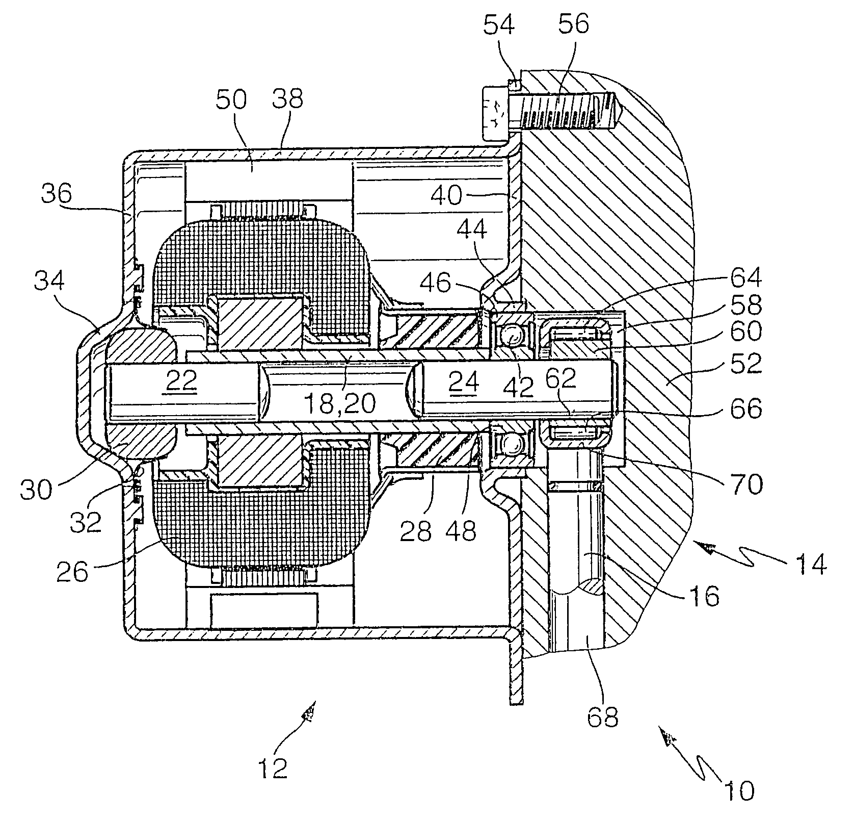
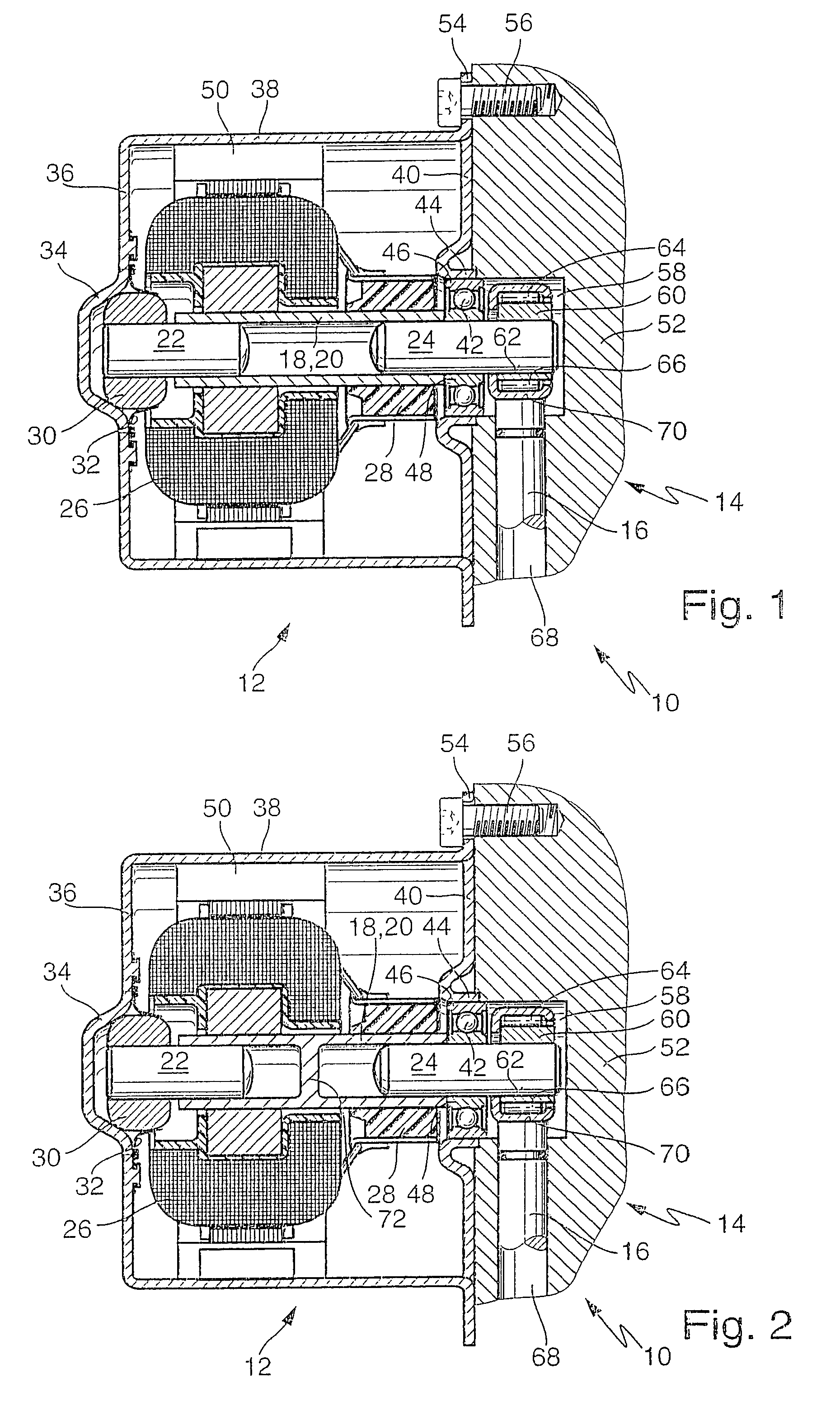
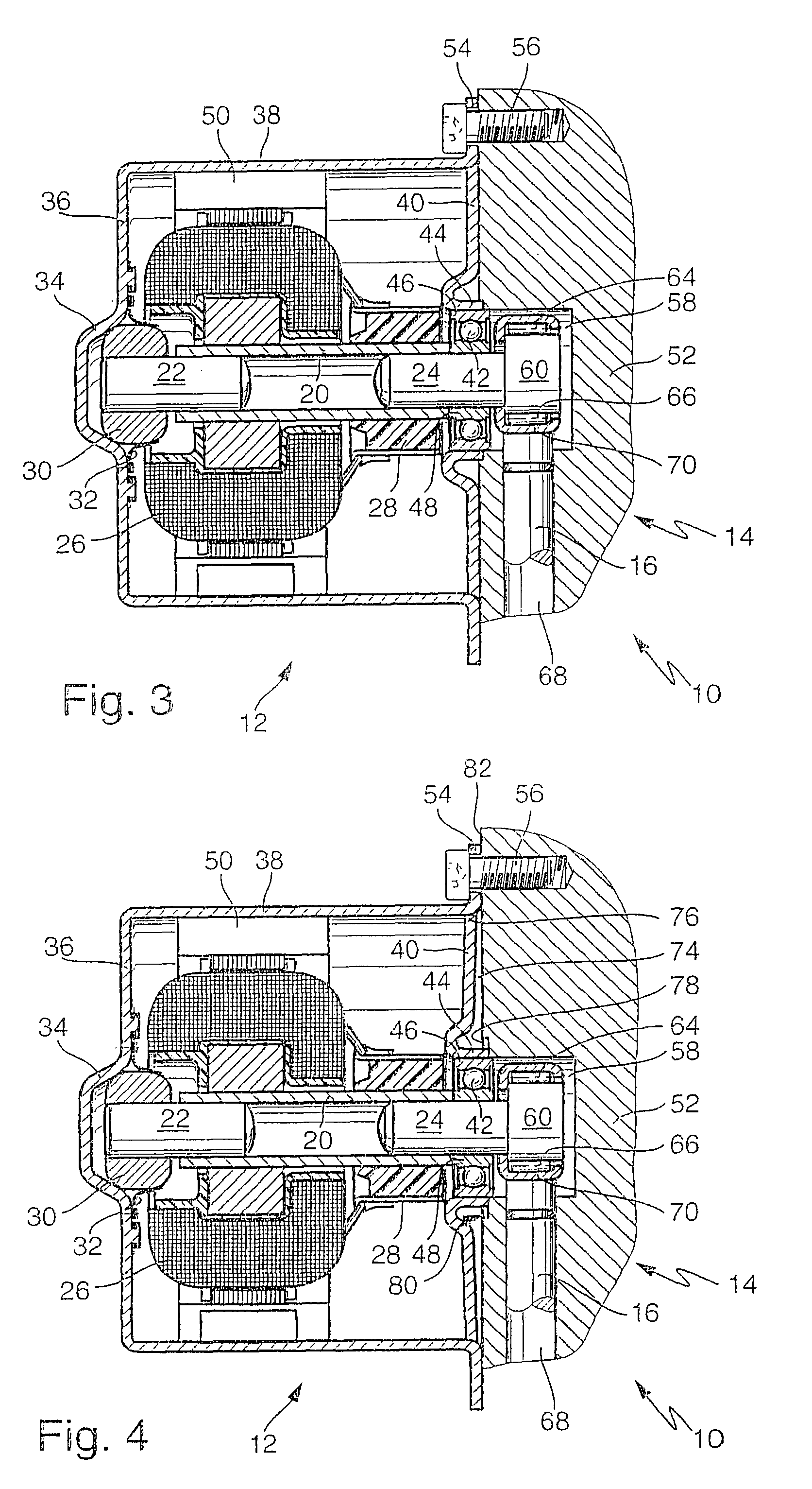
[0025]The pump unit of the invention shown in FIG. 1 and identified overall by reference numeral 10 has an electric motor 12 and a pump, embodied as a radial piston pump 14, which can be driven by the electric motor 12. The radial piston pump 14 has two pump pistons 16, which are disposed in a boxer arrangement, that is, facing one another. The sectional view shown in the drawing is at an angle of 90° from an imaginary center axis of the pump unit 10, so that only one of the two pump pistons 16 is visible.

[0026]The pump unit 10 has a rotor shaft 18, which at the same time forms a motor shaft of the electric motor 12. The rotor shaft 18 has a hollow shaft 20, into both ends of which pins 22, 24 are press-fitted. As a result of the press-fitting, the pins 22, 24 are joined in a manner fixed against relative rotation and fixed axially to the hollow shaft 20 of the rotor shaft 18. The hollow shaft 20 is cut from a piece of precision steel pipe and otherwise is not machined. The two pins...


PUM


Abstract

A pump unit for a hydraulic vehicle brake system with traction control has an electric motor driving a radial piston pump. A rotor shaft of the pump unit has a hollow shaft with two standardized, hardened cylindrical pins that are press-fitted into the ends of the hollow shaft. The rotor shaft can be produced simply, economically, and without metal-cutting machining. The hollow shaft has high bending and torsional strength. The rotor shaft has a small diameter at the bearing points, which makes a small bearing diameter and thus a small installation space for the pump unit possible.

Description

CROSS-REFERENCE TO RELATED APPLICATIONS[0001]This application is a 35 USC 371 application of PCT / DE 01 / 02812 filed on Jul. 25, 2001.BACKGROUND OF THE INVENTION[0002]1. Field of the Invention[0003]The invention relates to an improved pump unit for a hydraulic vehicle brake system.[0004]2. Description of the Prior Art[0005]One pump unit, known from German Patent DE 198 09 571 C1, unit has an electric motor as well as a pump that can be driven with the electric motor. The pump of the known pump unit is embodied as a radial piston pump. The known pump unit has a rotor shaft, which is driven to rotate by the electric motor and which drives the pump. The rotor shaft is embodied as a hollow shaft. On an end remote from the pump, the rotor shaft is supported rotatably in a motor housing of the electric motor. An end toward the pump of the rotor shaft embodied as a hollow shaft is press-fitted, in a manner fixed against relative rotation, into an eccentric bush of the pump. The eccentric bus...

Claims


Application Information

Patent Timeline
Patent Type & Authority Patents(United States)
IPC IPC(8): F04B17/00F04B35/04B60T8/40B60T17/00F04B17/03F04B53/00H02K5/173H02K7/00H02K7/075H02K7/08
CPCB60T8/4022F04B17/03H02K7/083H02K7/00H02K7/075B60T8/40
Inventor SIEGEL, HEINZALAZE, NORBERTMERKLEIN, DIETERSCHLITZKUS, MICHAELWEH, ANDREASBAREISS, ALEXANDER
Owner ROBERT BOSCH GMBH
Why Eureka
Try Eureka