Stagnation point reverse flow combustor for a combustion system

a combustion system and reverse flow technology, applied in the field of combustion systems, can solve the problems of large pressure loss in the process, environmental pollution, pollution raising public concerns,

Inactive Publication Date: 2007-01-30
GEORGIA TECH RES CORP
View PDF50 Cites 54 Cited by
  • Summary
  • Abstract
  • Description
  • Claims
  • Application Information

AI Technical Summary

Problems solved by technology

However, with the prevalent occurrences of combustion, one of the major downsides of these processes is environmental pollution.
Such pollutants have raised public concerns.
Also, the system requires high flow velocity of the fuel jets to create the pump action necessary for mixing the fuel with the hot combustion products.
Additionally, since a significant fraction of the large kinetic energy of the injected reactants jets is dissipated within the furnace, the process experiences large pressure losses.
Consequently, in its current design, this process is not suitable for application to land-based gas turbines and aircraft engine's combustors and other processes which require high combustion intensity and / or low pressure losses.
The design of a gas turbine combustor is complicated by the necessity for the gas turbine engine to operate reliably with a low level of emissions at a variety of power levels.
Low power operation at lower combustion temperatures tends to increase the generation of carbon monoxide and unburned hydrocarbons due to incomplete combustion of the fuel.
A relatively rich fuel / air mixture will improve the stability of the combustion process but will have an adverse affect on the level of emissions.
A primary problem with most combustion systems as mentioned above is the generation of pollutants such as NOx among others during the combustion of the fuel and air.
While suitable for their intended purposes, such systems utilize complicated structures to mix the air and fuel and are not always effective in their mixing.
Furthermore, reducing the oxidants generally results in higher combustion process temperatures which produce higher NOx emissions.

Method used


Image

  • Stagnation point reverse flow combustor for a combustion system
  • Stagnation point reverse flow combustor for a combustion system
  • Stagnation point reverse flow combustor for a combustion system

Examples


first embodiment

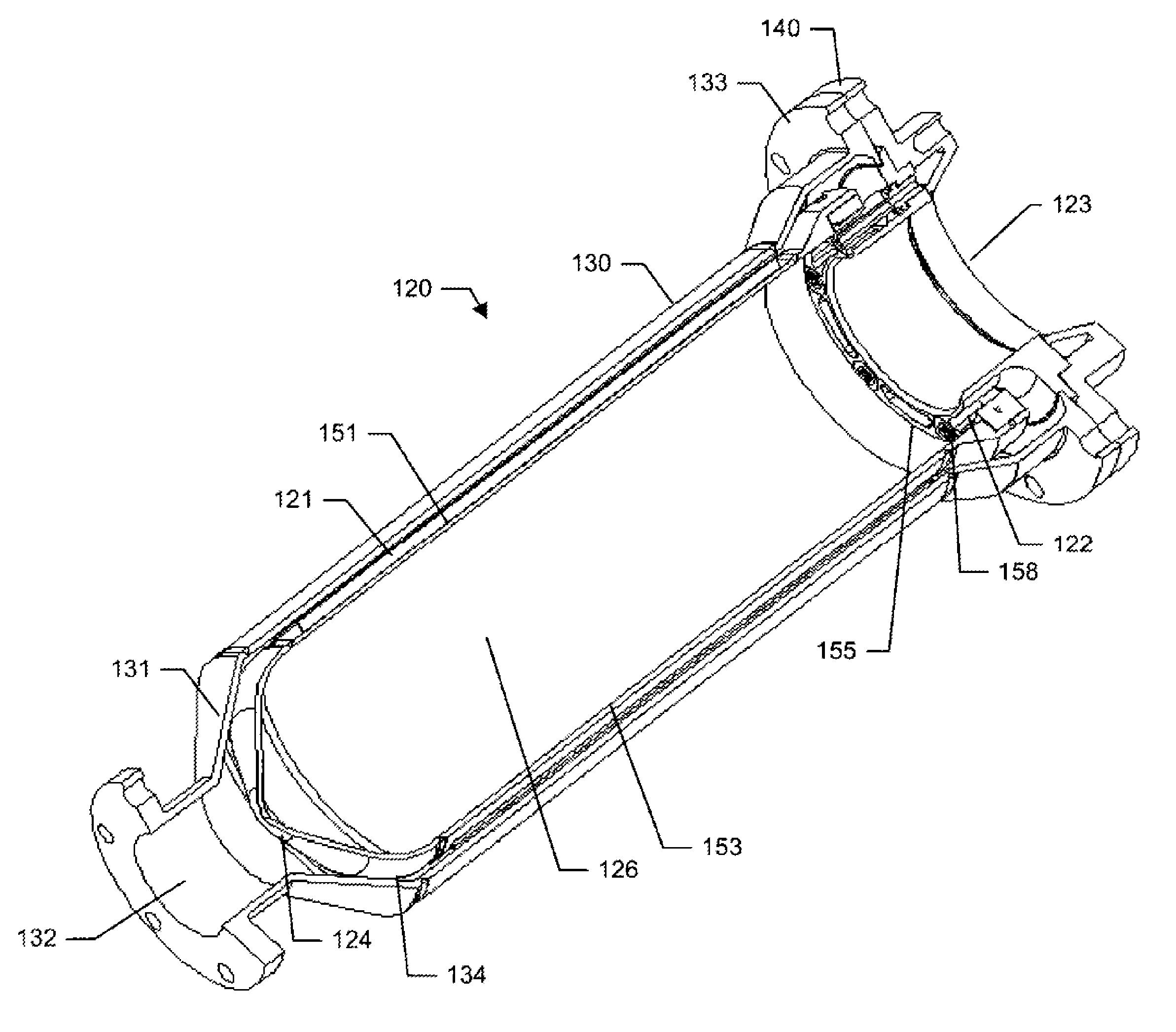
[0065]FIGS. 11 and 12 illustrate a combustor assembly 120 for implementing the above described technology into a combustion system such as a boiler or a gas turbine. FIGS. 13–17 illustrate a combustor assembly for use in a jet engine system. Combustor assembly 120 includes primary combustor vessel 121 which has a proximate end 122 and a distal closed end 124 defining a combustion chamber 126. Proximate end 122 may define combustion products exit opening 123. Combustion products exit opening 123 is preferably concentrically positioned within vessel 121. Reactants, which primarily are a fuel supply and an oxidant supply are provided into the combustion chamber for combustion. The fuel may be either in a gas or liquid state and the oxidant from an oxidant supplier which is preferably compressed air from a compressor but may be from any external source such as a fan. An igniter (not shown) ignites the reactants creating a flame and combustion products. Due to the geometry of primary com...

second embodiment

[0069]FIGS. 13–17 illustrate the combustor assembly for use with a turbine system incorporating a shaft for driving a compressor. In this embodiment, outer casing or secondary housing 130 includes an outer sleeve 172 and an inner sleeve 173. Inner sleeve 173 is offset from outer sleeve 172 defining a combustor vessel cavity 174 for receiving combustor vessel 180. Internal sleeve 173 is preferably cylindrical having an interior defining a shaft channel 175 for receiving turbine compressor shaft 176. Combustor vessel 180 is preferably a torus. The torus configuration defines an interior wall 186 and an exterior wall 188 both having an interior portion and is positioned within combustor vessel cavity 174 such that an outer air channel 182 is defined between the exterior wall of combustor vessel 180 and outer sleeve 172 and an inner air channel 184 is defined between the interior wall of combustor vessel 180 and inner sleeve 173. Also air-fuel manifold consists of a first air-fuel manif...


PUM


Abstract

A combustor assembly includes a combustor vessel having a wall, a proximate end defining an opening and a closed distal end opposite said proximate end. A manifold is carried by the proximate end. The manifold defines a combustion products exit. The combustion products exit being axially aligned with a portion of the closed distal end. A plurality of combustible reactant ports is carried by the manifold for directing combustible reactants into the combustion vessel from the region of the proximate end towards the closed distal end.

Description

BENEFIT CLAIMS TO PRIOR APPLICATIONS[0001]This application claims the benefit of U.S. Provisional Application No. 60 / 578,554 filed on Jun. 10, 2004 and is a continuation in part of U.S. Utility application Ser. No. 10 / 927,205 filed on Aug. 26, 2004.GOVERNMENT INTERESTS[0002]This invention was made in part during work supported by the U.S. Government, including grants from the National Aeronautics and Space Administration (NASA), #NCC3-982. The government may have certain rights in the invention.FIELD OF THE INVENTION[0003]This invention relates to a combustion system in general and more particularly to a combustion system which utilizes a combustion chamber design for low pollutant emissions by creating a stagnation region for anchoring a flame and reverse flow of combustion products that partially mixes with the incoming reactants.BACKGROUND[0004]Combustion and its control are essential features to everyday life. Approximately eighty-five percent of the energy used in the United St...

Claims


Application Information

Patent Timeline
Patent Type & Authority Patents(United States)
IPC IPC(8): F23D14/46F02C1/00F23R3/58F23C5/24F23C9/00F23L1/00F23M3/00F23R3/42F23R3/54
CPCF23C5/24F23C9/006F23R3/54F23D14/66F23D17/002F23R3/42F23D14/22F23C2900/03006Y02E20/34
Inventor ZINN, BEN T.NEUMEIER, YEDIDIASEITZMAN, JERRY M.JAGODA, JECHIELHASHMONAY, BEN-AMI
Owner GEORGIA TECH RES CORP
Why Eureka
Try Eureka