Accurate alignment of an LED assembly

a technology of led assembly and accurate alignment, which is applied in the field of accurate mounting of leds, can solve the problems of electrical shorts and affecting the optical performance of the device, and achieve the effect of the same shape and area

Inactive Publication Date: 2007-01-30
LUMILEDS
View PDF16 Cites 27 Cited by
  • Summary
  • Abstract
  • Description
  • Claims
  • Application Information

AI Technical Summary

Benefits of technology

[0003]In one embodiment of the invention, an LED assembly includes a heat sink and a submount. The heat sink has a top mating surface that is solder wettable and the submount has a bottom mating surface that is solder wettable. The top and bottom mating surfaces have substantially the same shape and area. The submount is soldered atop the heat sink. During a reflow process, the molten solder causes the submount to align with the top mating surface of the heat sink.

Problems solved by technology

Epoxy attached devices, however, have various drawbacks: (a) the epoxy has an inherently weak thermal conducting property that leads to higher package thermal resistance; (b) poor alignment between the mating parts that leads to compromised optical performance of the device; and (c) formation of a fillet on the side of the chip that can lead to an electrical short.

Method used


Image

  • Accurate alignment of an LED assembly
  • Accurate alignment of an LED assembly
  • Accurate alignment of an LED assembly

Examples


Embodiment Construction

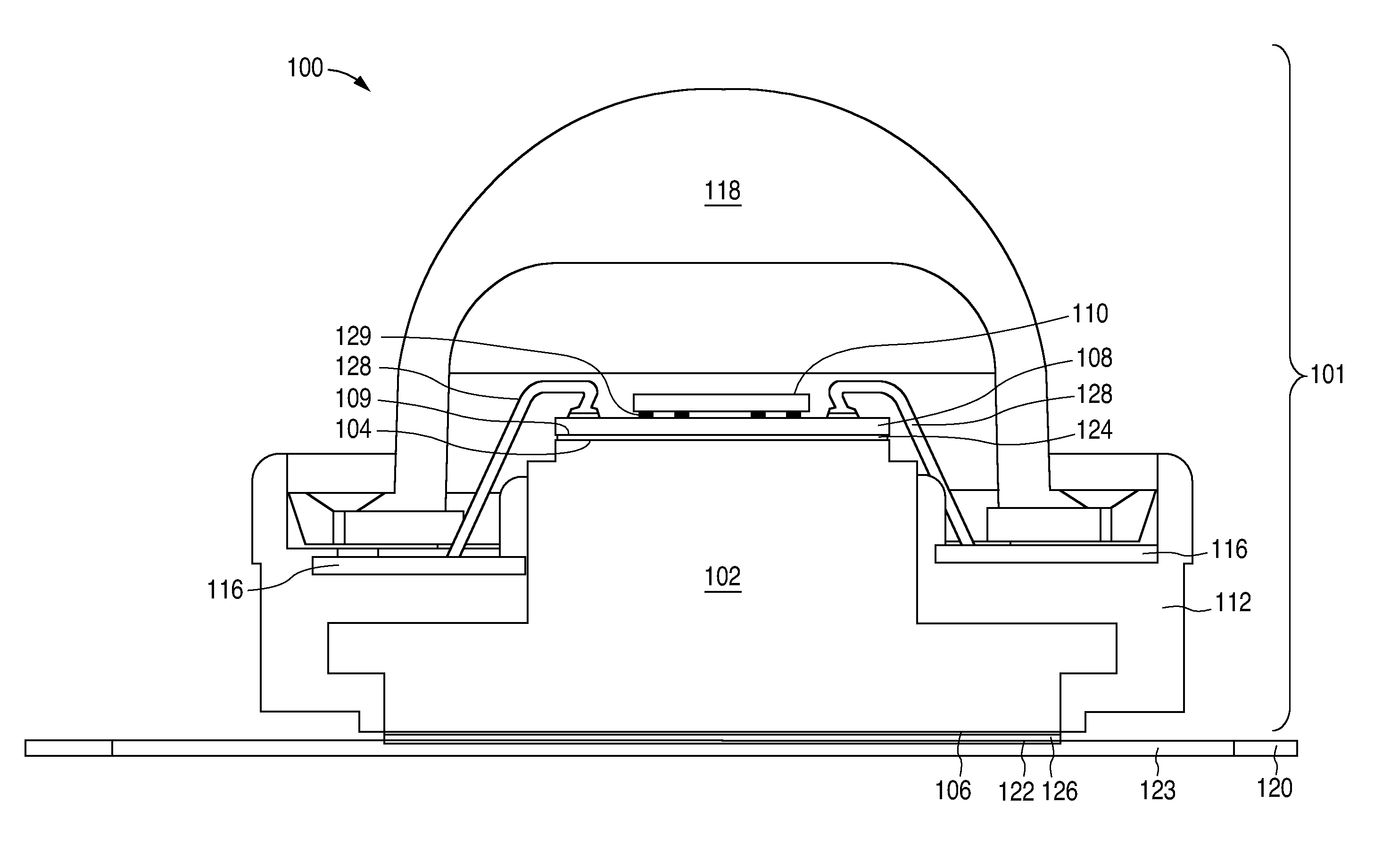
[0007]In one embodiment of the invention, a submount is mounted on a heat sink with solder instead of epoxy. The submount has a solderable bottom mating surface and the heat sink has a solderable top mating surface of substantially the same shape and area. During a solder reflow, the molten solder causes the submount to align with the heat sink. Furthermore, the heat sink is mounted on a substrate with solder instead of epoxy. The heat sink has a solderable bottom mating surface and the substrate has a solderable top mating surface of substantially the same shape and area. Again, during a solder reflow, the molten solder causes the heat sink to align with the substrate.

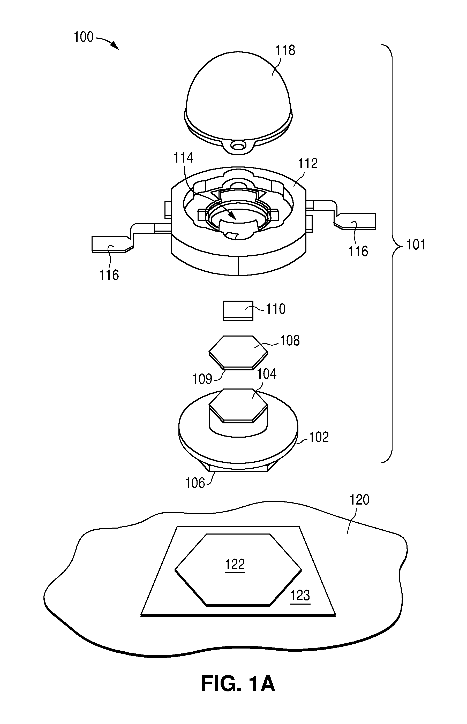
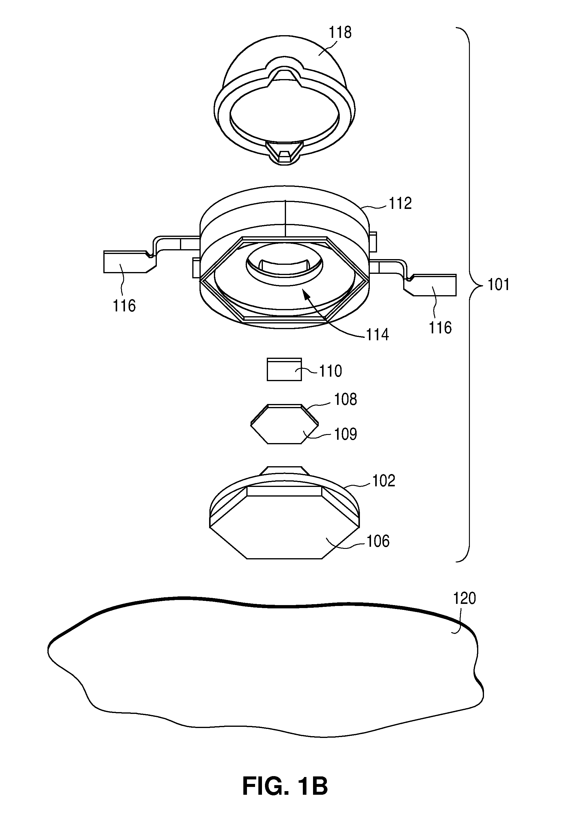
[0008]FIGS. 1A and 1B illustrate exploded views of an LED assembly 100 in one embodiment. FIG. 2 illustrates a cross-section view of an assembled LED assembly 100. LED assembly 100 includes an LED package 101 and a substrate 120.

[0009]LED package 101 includes an LED die 110 that is mounted on a submount 108. Submount ...


PUM

PropertyMeasurementUnit
areaaaaaaaaaaa
shapeaaaaaaaaaa
liquidous temperatureaaaaaaaaaa

Abstract

An LED assembly includes a heat sink and a submount. The heat sink has a top mating surface that is solder wettable, and the submount has a bottom mating surface that is solder wettable. The top and the bottom mating surfaces have substantially the same shape and area. The submount is soldered atop the heat sink. During solder reflow, the molten solder causes the submount to align with the top mating surface of the heat sink. The LED assembly may further include a substrate having a top mating surface, and the heat sink may further include a bottom mating surface. The top and bottom mating surfaces have substantially the same shape and area. The heat sink is soldered atop the substrate. During solder reflow, the molten solder causes the heat sink to align with the top mating surface of the substrate.

Description

FIELD OF INVENTION[0001]This invention relates to LEDs (light emitting diodes), and specifically to the accurate mounting of LEDs.DESCRIPTION OF RELATED ART[0002]Optical light sources such as III-nitride LEDs are sometimes mounted in a “flip chip” approach on an intermediate material or submount such as silicon. The entire package is designed to enhance the total light generating capability as well as for low thermal resistance to allow for high current density operation. Usually an epoxy compound is used to attach the submount onto a heat sink to provide support and a thermal path between the flip chip device and the LED package. A similar epoxy compound is then used to attach the LED package to the customer's wiring board. Epoxy attached devices, however, have various drawbacks: (a) the epoxy has an inherently weak thermal conducting property that leads to higher package thermal resistance; (b) poor alignment between the mating parts that leads to compromised optical performance o...

Claims


Application Information

Patent Timeline
Patent Type & Authority Patents(United States)
IPC IPC(8): H01L23/495H01L33/56H01L33/58H01L33/64
CPCH01L33/642H01L33/56H01L2224/48465H01L33/58
Inventor ELPEDES, CRESENTE S.FITERI BIN AZIZ, ZAINULMARTIN, PAUL S.
Owner LUMILEDS
Why Eureka
Try Eureka