Electromagnetic MWD telemetry system incorporating a current sensing transformer

a technology of current sensing transformer and mwd telemetry, which is applied in the field of electromagnetic mwd telemetry system incorporating a current sensing transformer, can solve the problems of low data transmission rate, inability to provide data in real time, and small signal-to-noise ratio, and achieve the effect of improving the signal-to-noise ratio

Inactive Publication Date: 2007-01-30
WEATHERFORD CANADA PARTNERSHIP
View PDF16 Cites 32 Cited by
  • Summary
  • Abstract
  • Description
  • Claims
  • Application Information

AI Technical Summary

Benefits of technology

[0010]The present invention is an electromagnetic telemetry system for transmitting data from a downhole assembly, which is operationally attached to a drill string, to a telemetry receiver system. The data are typically representative of a response of one or more sensors disposed within the downhole assembly. A downhole transmitter creates a signal current within the drill string. The signal current is modulated to represent the transmitted data. Signal current is then measured directly with a telemetry receiver system. The telemetry receiver system includes a transformer that surrounds the path of the current, and a receiver. The transformer preferably comprises a toroid that responds directly to the induced signal current. Output from the transformer is input to the receiver located remote from the downhole assembly and typically at the surface of the earth. Alternately, voltages resulting from the signal current can be measured with a rig voltage receiver and combined with the direct current measurements to enhance signal to noise ratio.

Problems solved by technology

Alternately, sensor response data can be stored in the downhole assembly, but these data are not available in “real time” since they can be retrieved only after the downhole assembly has been returned or “tripped’ to the surface of the earth.
Data transmission rates are low using mud pulse systems Furthermore, the signal to noise ratio is typically small and signal attenuation is large, especially for relatively deep boreholes.

Method used


Image

  • Electromagnetic MWD telemetry system incorporating a current sensing transformer
  • Electromagnetic MWD telemetry system incorporating a current sensing transformer
  • Electromagnetic MWD telemetry system incorporating a current sensing transformer

Examples


Embodiment Construction

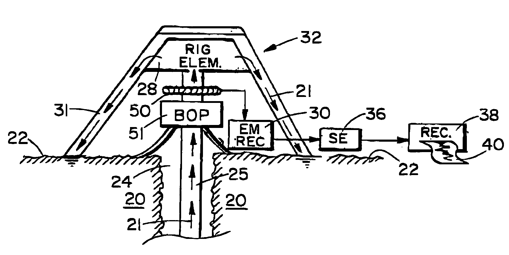
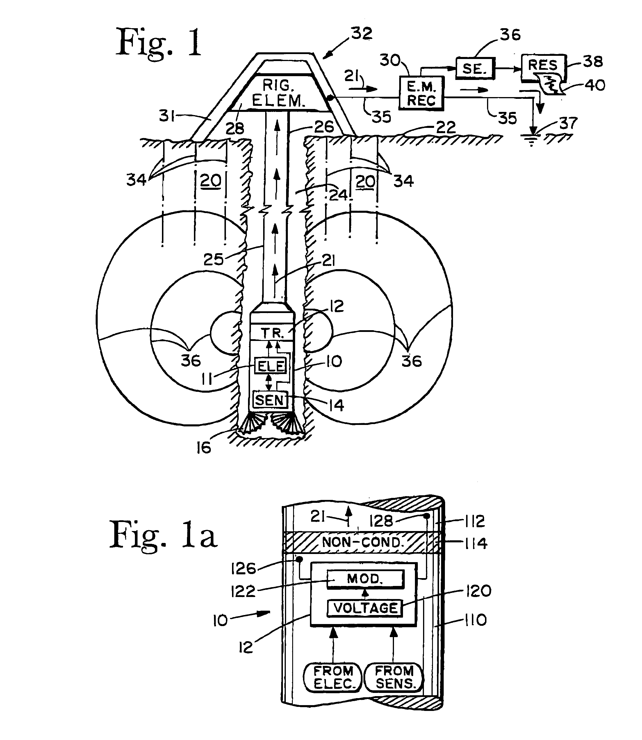
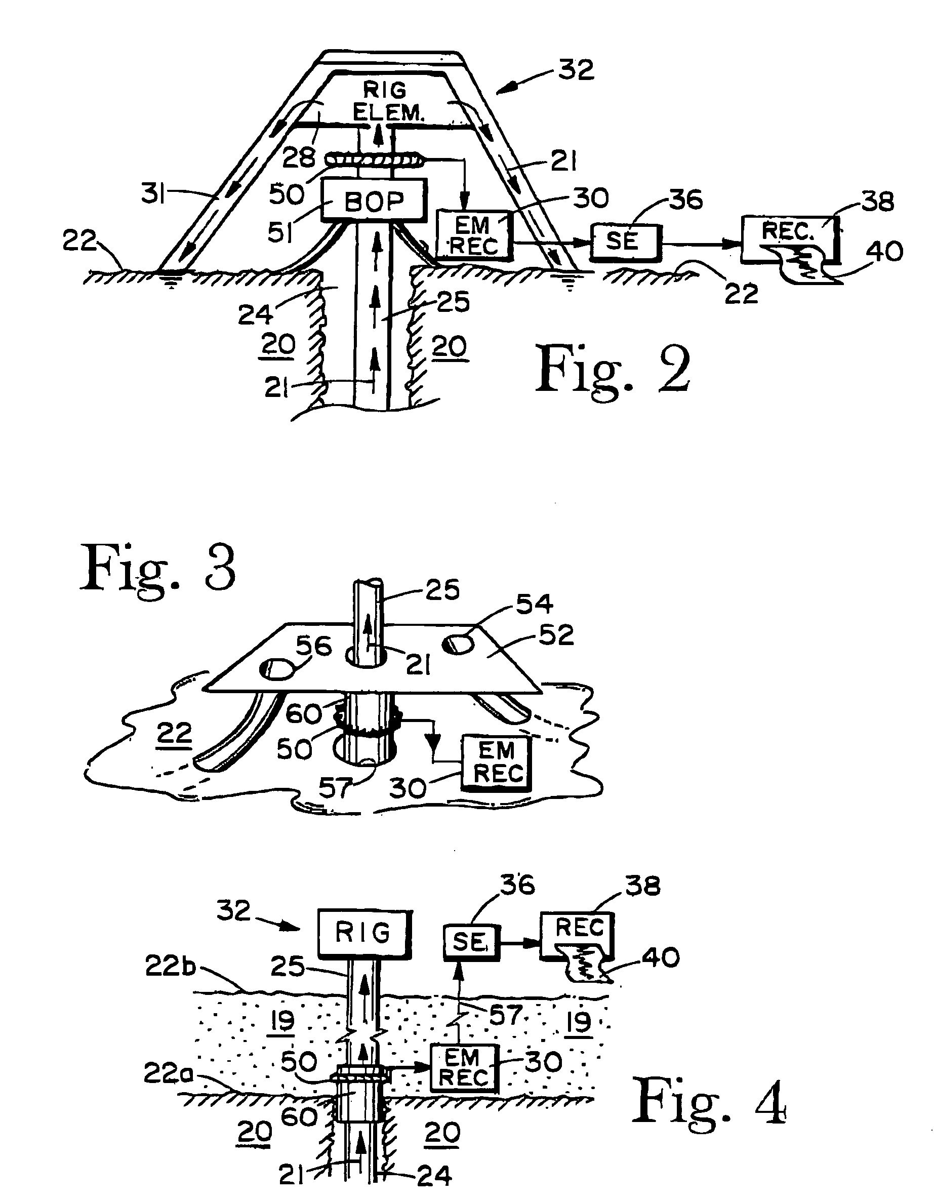
[0022]FIG. 1 illustrates an electromagnetic (EM) telemetry system embodied in a MWD system. A downhole assembly 10 is shown disposed in a well borehole 24 which penetrates earth formation 20. The upper end of the downhole assembly 10 is operationally attached to a lower end of a drill string 25. The lower end of the borehole assembly is terminated by a drill bit 16. The upper end of the drill string 25 terminates at a rotary drilling rig assembly 32 positioned at the surface 22 of the earth. The rotary drilling rig comprising a derrick 31 and rig elements 28. Elements not shown but included in the rig elements 28 are drilling fluid pumping and circulation equipment, draw works, a motor operated rotary table, a cooperating kelly, and other elements known in rotary drilling. The drilling rig rotates the drill string and attached drill bit 16 thereby advancing the borehole 24.

[0023]Still referring to FIG. 1, the downhole assembly comprises an EM transmitter 12 which creates a “signal” ...


PUM


Abstract

An electromagnetic telemetry system for transmitting data from a downhole assembly, which is operationally attached to a drill string, to a telemetry receiver system. The data are typically responses of one or more sensors disposed within the downhole assembly. A downhole transmitter induces a signal current within the drill string. The signal current is modulated to represent the transmitted data. Induced signal current is measured directly with the telemetry receiver system. The telemetry receiver system includes a transformer that surrounds the path of the current, and an electromagnetic current receiver. The transformer preferably comprises a toroid that responds directly to the induced signal current. Output from the transformer is input to an electromagnetic current receiver located remote from the downhole assembly and typically at the surface of the earth. Alternately, voltage resulting from the induced signal current can be measured with a rig voltage receiver and combined with the direct current measurements to enhance signal to noise ratio.

Description

[0001]This invention is directed toward geophysical measurement apparatus and methods employed during the drilling of a well borehole. More specifically, the invention is directed toward an electromagnetic telemetry system for transmitting information from a downhole assembly, which is operationally attached to a drill string, to the surface of the earth. A transmitter induces a current, indicative of the information, within the drill sting. The current is measured with a receiver located remote from the downhole assembly, and the desired information is extracted from the current measurement.BACKGROUND OF THE INVENTION[0002]Systems for measuring geophysical and other parameters within and in the vicinity of a well borehole typically fall within two categorizes. The first category includes systems that measure parameters after the borehole has been drilled These systems include wireline logging, tubing conveyed long, slick line logging, production logging, permanent downhole sensing ...

Claims


Application Information

Patent Timeline
Patent Type & Authority Patents(United States)
IPC IPC(8): G01V3/00E21B47/12
CPCE21B47/122E21B47/13E21B47/12
Inventor WISLER, MACMILLANJIAN-QUN, WUWEISBECK, DENIS
Owner WEATHERFORD CANADA PARTNERSHIP
Why Eureka
Try Eureka