System and method for post filtering peak power reduction in communications systems

a technology of post filtering and peak power reduction, applied in the field of communication systems, can solve the problems of high peak-to-average ratio, inconvenient operation, and inability to slow down the trend, so as to reduce the output signal, and reduce the output communication signal

Active Publication Date: 2007-01-30
INTEL CORP
View PDF47 Cites 29 Cited by
  • Summary
  • Abstract
  • Description
  • Claims
  • Application Information

AI Technical Summary

Benefits of technology

[0014]In a first aspect the present invention provides a communication system comprising a communication signal source providing a band limited communication signal; for example, the communication system may be a multi-carrier communication system or a spread spectrum communication system. A peak reduction unit is coupled to receive the band limited communication signal and provide a band limited peak reduced output signal. The peak reduction unit comprises a circuit for providing a peak reduction correction waveform corresponding to the difference between the communication signal and the communication signal hard limited to a limit value and a correction filter for filtering the peak reduction correction waveform and providing a band limited peak reduction correction signal corresponding to the band limits of the communication signal. A combiner receives the band limited communication signal and the band limited peak reduction correction signal and combines them to provide a band limited peak reduced output signal. The peak reduction unit also preferably comprises a delay for delaying the band limited communication signal and providing the delayed signal to the combiner. The communication system may further comprise a digital-to-analog conversion stage for converting the peak reduced output signal to an analog signal, a power amplifier receiving and amplifying the analog signal, and an antenna coupled to the output of the power amplifier.
[0015]In a further aspect, the present invention provides a peak reduction unit adapted for use in a communication system. The peak reduction unit comprises a first signal path and a second parallel signal path. The first signal path receives a band limited input signal and includes a delay circuit for delaying the input signal. The second parallel signal path also receives the band limited input signal and includes a peak reduction calculation unit for calculating a peak reduction correction and a filter providing a filtering operation on the peak reduction correction. The peak reduction unit further comprises a combiner combining the filtered peak reduction correction and delayed input signal and providing peak adjusted output signals.
[0016]In a preferred embodiment of the peak reduction unit, the second signal path further comprises a signal magnitude detector, a comparator for comparing the signal magnitude to a predetermined limit value and a switch coupled to the output of the comparator and the peak reduction calculation unit for selecting the peak reduction correction if the signal magnitude exceeds the predetermined limit value. The second signal path may also include a gain circuit for adjusting the magnitude of the correction by a gain value. The gain circuit may comprise a multiplier receiving the peak reduction correction signal and multiplying it by the gain value. The gain value should be less than 1 when the peak impulse response of the correction filter is normalized to 1. In a more general case the gain value should be greater than zero but

Problems solved by technology

These wireless systems are being placed under increasing performance demands that are taxing the capability of available equipment, especially wireless base station equipment.
The increasing number of wireless users is of course readily apparent and this trend is unlikely to slow due to the convenience of wireless services.
High peak-to-average ratios require increased cost in these components.
Increased carrier bandwidth may cause operation outside government allocated operating bands in violation of the law.
The subsequent filtering introdu

Method used


Image

  • System and method for post filtering peak power reduction in communications systems
  • System and method for post filtering peak power reduction in communications systems
  • System and method for post filtering peak power reduction in communications systems

Examples


Embodiment Construction

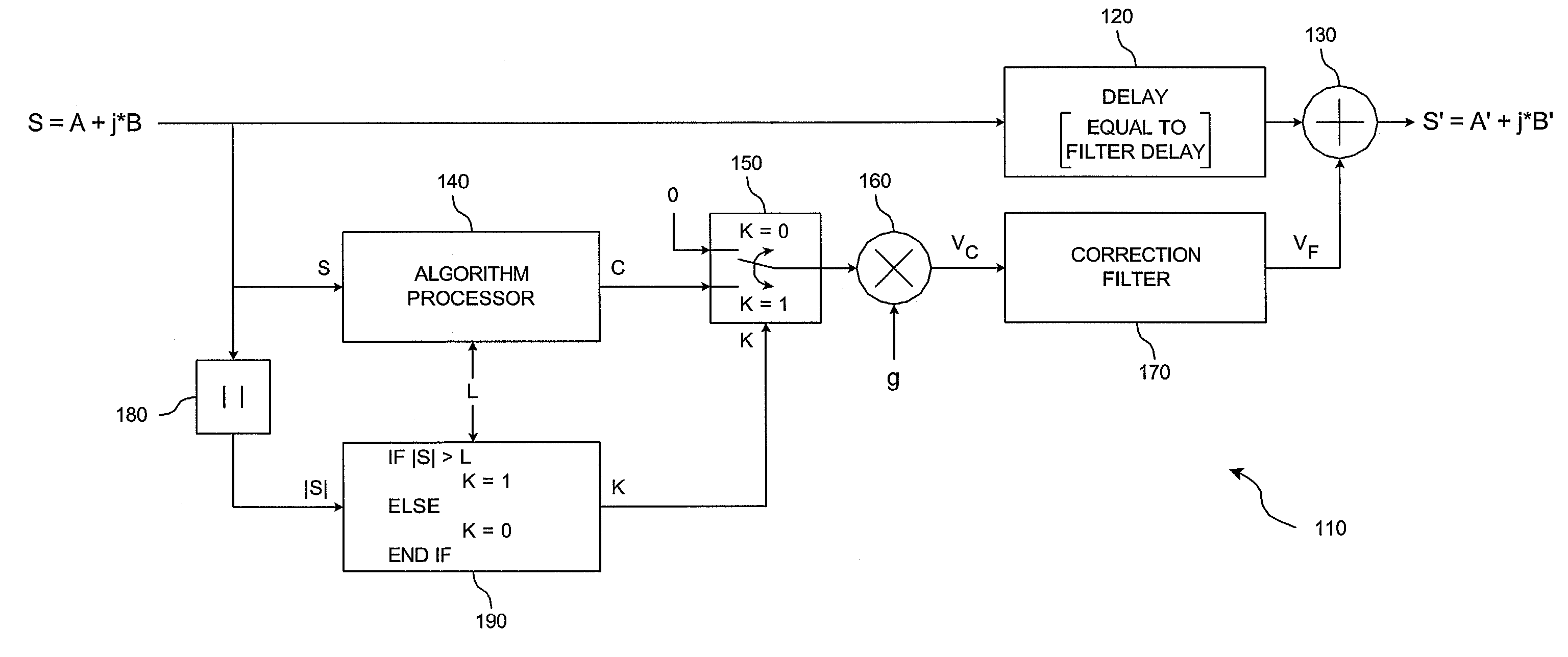
[0031]A preferred embodiment of a single carrier communications system employing signal-peak suppression (or reduction) in accordance with the present invention is illustrated in FIG. 4. A preferred embodiment of a multiple carrier communications system employing signal-peak suppression in accordance with the present invention is illustrated in FIG. 5.

[0032]Referring to FIG. 4, a communication signal, which may comprise a digitally sampled signal stream represented by an in-phase component signal stream A and a quadrature-phase component signal stream B, is input to a signal-peak suppression unit 110. This digitally sampled signal stream may contain one or more communications channels as produced by the signal generator 10 and filter 20. The signal-peak suppression unit outputs a peak-reduced signal stream represented by an in-phase component signal stream A′ and a quadrature component signal stream B′. This signal-peak suppression output signal is then D / A converted at D / A converte...


PUM


Abstract

A system and method for post filtering signal peak reduction adapted for use in a communication system incorporating a source of a communication signal band limited in a manner corresponding to a spectral band to which the communication system is limited. A first signal path receives as an input the band limited communication signal. A second parallel signal path includes a peak reduction calculation unit for calculating a peak reduction correction signal and a filter providing a filtering operation on the peak reduction correction signal corresponding to the spectral band to which the communication system is limited. The filtered peak reduction correction signal and delayed input signal are combined to provide peak adjusted output signals without violating the band limits of the communication signal or the modulation scheme of the communication signal.

Description

RELATED APPLICATION INFORMATION[0001]The present application claims priority under 35 USC §119 (e) of provisional application Ser. No. 60 / 302,565 filed Jul. 2, 2001, the disclosure of which is incorporated herein by reference in its entirety.BACKGROUND OF THE INVENTION[0002]1. Field of the Invention[0003]The present invention relates to communications systems that transmit signals that may be composed of one or more combined transmit carriers. Each of these carriers may include one or more communication channels. More particularly, the present invention relates to wireless communications systems and signal processing apparatus employed in wireless communications systems. The term ‘wireless communications systems’ includes cellular communication systems, personal communication systems (PCS), wireless local loop systems, and all other like systems.[0004]2. Background of the Prior Art and Related Information[0005]Wireless communications systems employing transmission between base stati...

Claims


Application Information

Patent Timeline
IPC IPC(8): H04L27/04H04B1/69H04L25/03H04B1/707H04L27/26
CPCH04B1/707H04L27/2614H04B2201/70706
Inventor HUNTON, MATTHEW J.
Owner INTEL CORP
Why Eureka
Try Eureka