Dynamic bass boost apparatus and method

a technology of dynamic bass and boost apparatus, which is applied in the direction of electrical transducers, transducer details, electrical apparatus, etc., can solve the problems of excessive cost, inability to produce a high-quality sound output, and excessive complexity

Active Publication Date: 2007-01-30
BOSTON ACOUSTICS INC
View PDF20 Cites 96 Cited by
  • Summary
  • Abstract
  • Description
  • Claims
  • Application Information

AI Technical Summary

Benefits of technology

[0007]In one embodiment, the variable filter comprises a high-pass, state variable filter. The control circuit may comprise a low-pass filter configured for passing the selected band and a detector configured for detecting the signal level in the selected band and for establishing time constants of the control signal. The control circuit may be configured to establish an inverse relationship between the quality factor of the variable filter and the detected signal level. More particularly, the control circuit may be configured to control bass audio frequencies to limit the Fletcher-Munson effect.

Problems solved by technology

All known dynamic bass boost circuits have had one or more drawbacks, including but not limited to excessive complexity, excessive cost and an inability to produce a high quality sound output.

Method used


Image

  • Dynamic bass boost apparatus and method
  • Dynamic bass boost apparatus and method
  • Dynamic bass boost apparatus and method

Examples


first embodiment

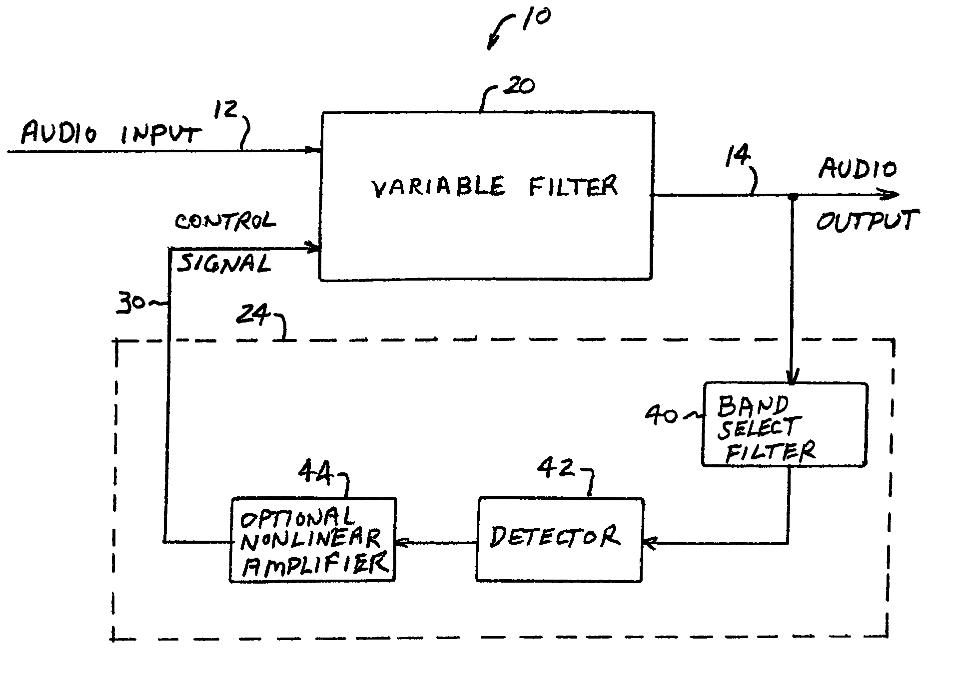
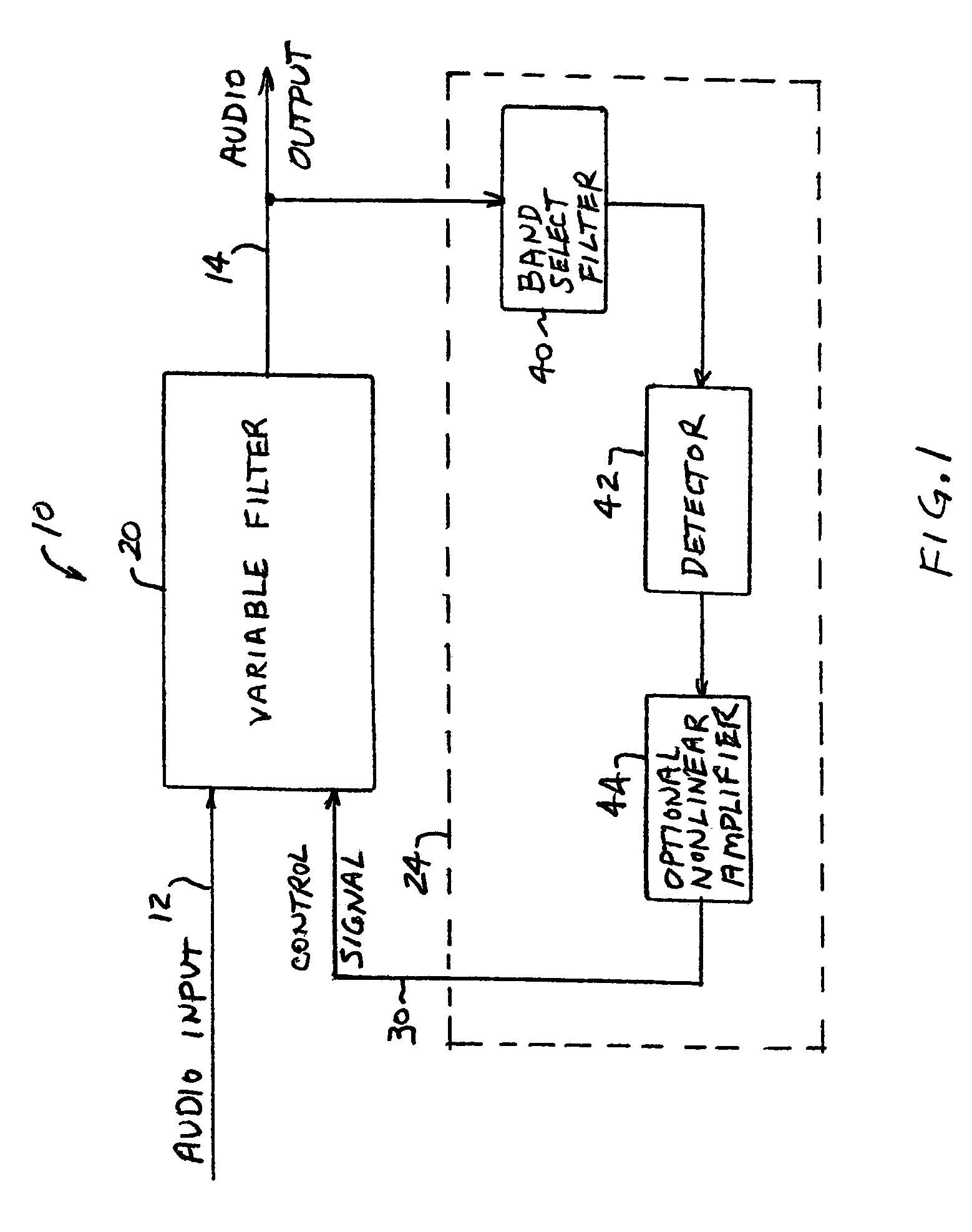
[0022]An audio processor, or dynamic bass boost circuit, in accordance with the invention is shown in FIG. 1. A dynamic bass boost circuit 10 receives an audio input signal 12 and provides a filtered audio output signal 14 having controlled bass frequencies so as to at least partially compensate for the Fletcher-Munson effect. Partial compensation for the Fletcher-Munson effect may include enhancement of only selected bass frequencies and / or less than full compensation for the Fletcher-Munson effect at one or more frequencies.

[0023]Dynamic bass boost circuit 10 includes a variable filter 20 and a control circuit 24. Control circuit 24 receives audio output signal 14 and provides a control signal 30 to variable filter 20. The control signal 30 controls the frequency characteristic of variable filter 20 as a function of volume level to at least partially compensate for the Fletcher-Munson effect.

[0024]Audio input signal 12 may be any suitable audio signal. For example, input signal 12...

second embodiment

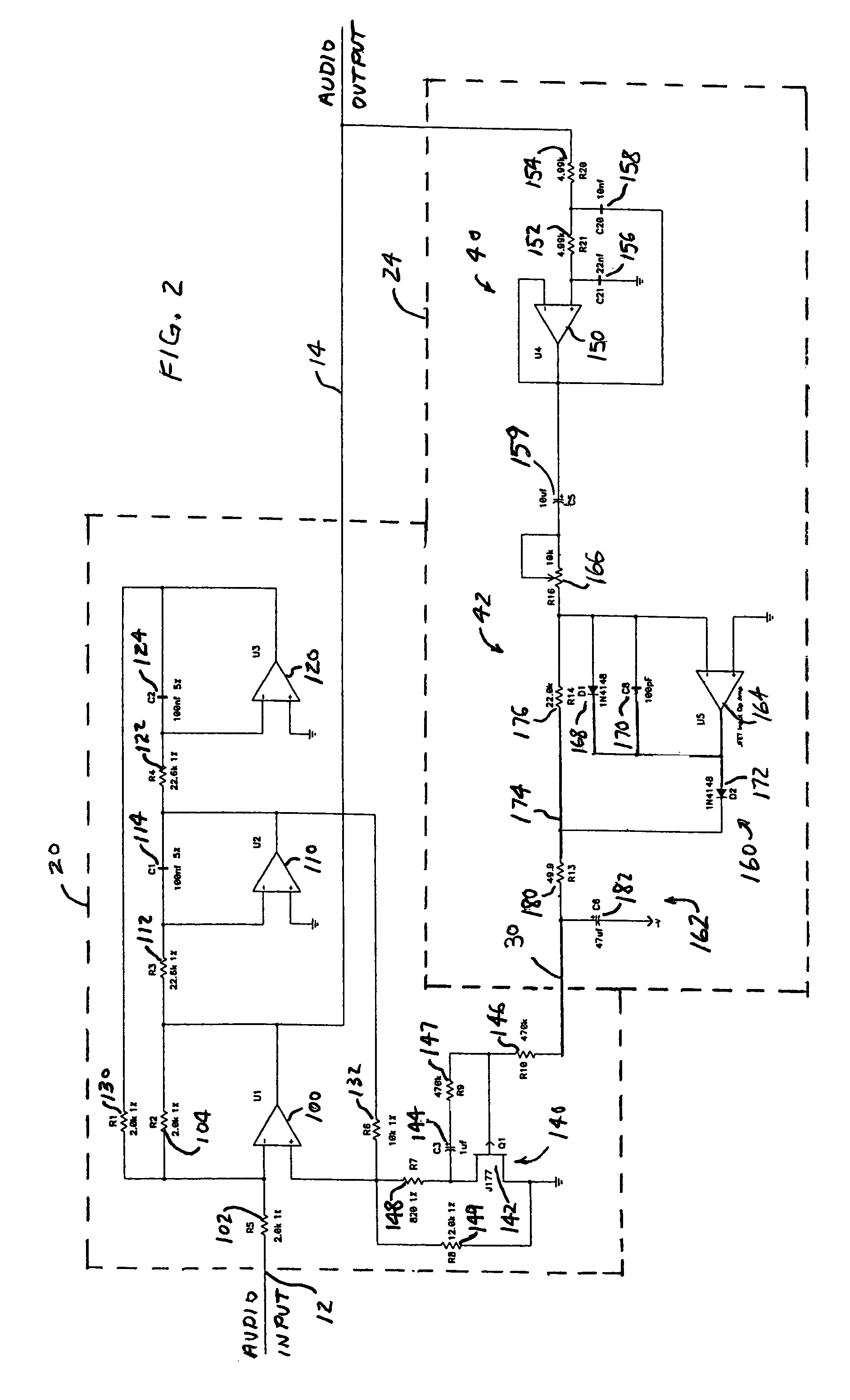
[0030]An audio processor in accordance with the invention is shown in FIG. 2. Like elements in FIGS. 1 and 2 have the same reference numerals. The embodiment of FIG. 2 is a specific implementation of the audio processor of FIG. 1, with non-linear amplifier 44 omitted.

[0031]In the embodiment of FIG. 2, variable filter 20 is a high-pass, state variable filter. The high-pass, state variable filter 20 includes operational amplifiers 100, 110, and 120 coupled in series. Operational amplifier 100 has an input resistor 102 and a feedback resistor 104, which form a summer. Operational amplifier 110 has an input resistor 112 and a feedback capacitor 114, which form a first integrator. Operational amplifier 120 has an input resistor 122 and a feedback capacitor 124, which form a second integrator. A feedback resistor 130 is connected between the output of amplifier 120 and the inverting input of amplifier 100. A feedback resistor 132 is coupled between the output of amplifier 110 and the non-...

third embodiment

[0060]A schematic block diagram of an audio processor in accordance with the invention as shown in FIG. 4. Like elements in FIGS. 1, 2 and 4 have the same reference numerals. The embodiment of FIG. 4 is another implementation of the audio processor of FIG. 1, with non-linear amplifier 44 omitted. In the embodiment of FIG. 4, voltage-controlled resistor circuit 140 (FIG. 2) is replaced with a resistor 200 connected between the non-inverting input of amplifier 100 and ground, and resistor 132 (FIG. 2) is replaced with a series gain / attenuation element 210 having a signal input connected to the output of amplifier 110 and a signal output connected to the non-inverting input of amplifier 100. The overall operation of the embodiment of FIG. 4 may be the same as the embodiment of FIG. 2, except as to series gain / attenuation element 210 and resistor 200 for controlling the quality factor of variable amplifier 20.

[0061]Control signal 30 is supplied from detector 42 to a control input of ser...


PUM


Abstract

Audio processing methods and apparatus are provided for at least partially compensating for the Fletcher-Munson effect. An audio processor includes a variable filter receiving an input signal and providing a filtered output signal, the variable filter having a fixed cutoff frequency and a quality factor that is controllable in response to a control signal, and a control circuit configured to detect a signal level representative of input signal level in a selected band and to generate the control signal in response to the detected signal level. The control circuit may include a low-pass band select filter and a detector for detecting a signal level in the band selected by the low-pass filter and for generating the control signal.

Description

FIELD OF THE INVENTION[0001]This invention relates to systems and methods for processing audio signals and, more particularly, to systems and methods for dynamically controlling the bass frequency band of audio signals as a function of volume level.BACKGROUND OF THE INVENTION[0002]The Fletcher-Munson effect is the name given to the well-known fact that human perception of sound in the bass frequency band (frequencies less than about 500 Hz) is influenced by the volume level of the sound. In particular, the sensitivity of a human listener to bass frequencies decreases as volume level decreases, while the sensitivity to higher frequencies decreases to a lesser degree. Accordingly, music played at low volume levels is perceived as lacking bass frequencies. The Fletcher-Munson effect can be compensated for by increasing the sound energy at low frequencies relative to the sound energy at higher frequencies.[0003]To achieve such compensation, audio filter circuits have been designed to in...

Claims


Application Information

Patent Timeline
Patent Type & Authority Patents(United States)
IPC IPC(8): H03G5/00H03G9/00H03G5/22H03G9/16
CPCH03G1/007H03G9/16H03G9/005H03G5/22
Inventor MARTIN, STEPHEN L.BURLINGAME, GREGORY B.DAVID, JOHN R.ROGGE, GLENN G.
Owner BOSTON ACOUSTICS INC
Why Eureka
Try Eureka