
Method for decreasing and compensating the transmission loss at a wavelength-division-multiplexed passive optical network and an apparatus therefor

a wavelength-division multi-plexed, optical network technology, applied in multiplex communication, transmission monitoring, instruments, etc., can solve the problem of additional optical loss, typically 3 db, and achieve the effect of reducing optical loss, increasing transmission distance, and improving transmission quality

Inactive Publication Date: 2007-01-30
KOREA ADVANCED INST OF SCI & TECH
View PDF3 Cites 35 Cited by
  • Summary
  • Abstract
  • Description
  • Claims
  • Application Information

AI Technical Summary

Benefits of technology

"The present invention aims to solve problems in optical networks by minimizing optical loss and improving transmission quality and distance. It presents a device and method for fault recovery without additional optical loss, as well as a method for decreasing and compensating optical loss in transmission paths."

Problems solved by technology

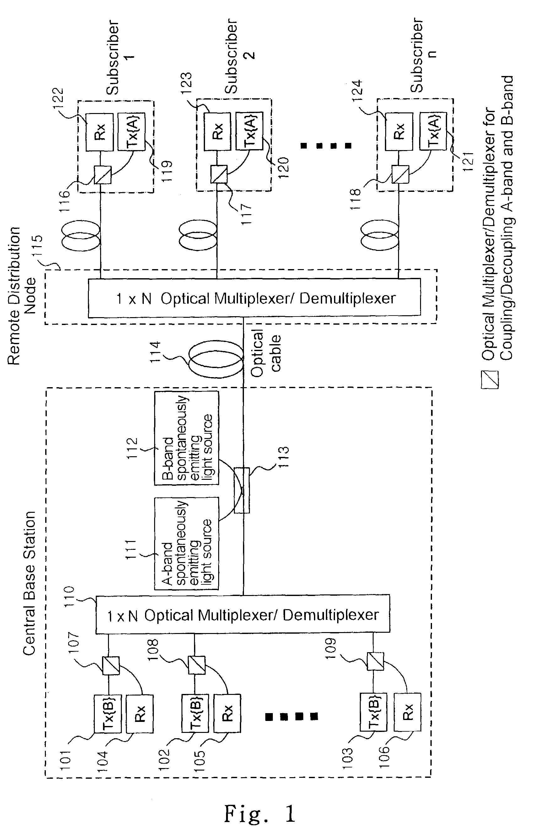
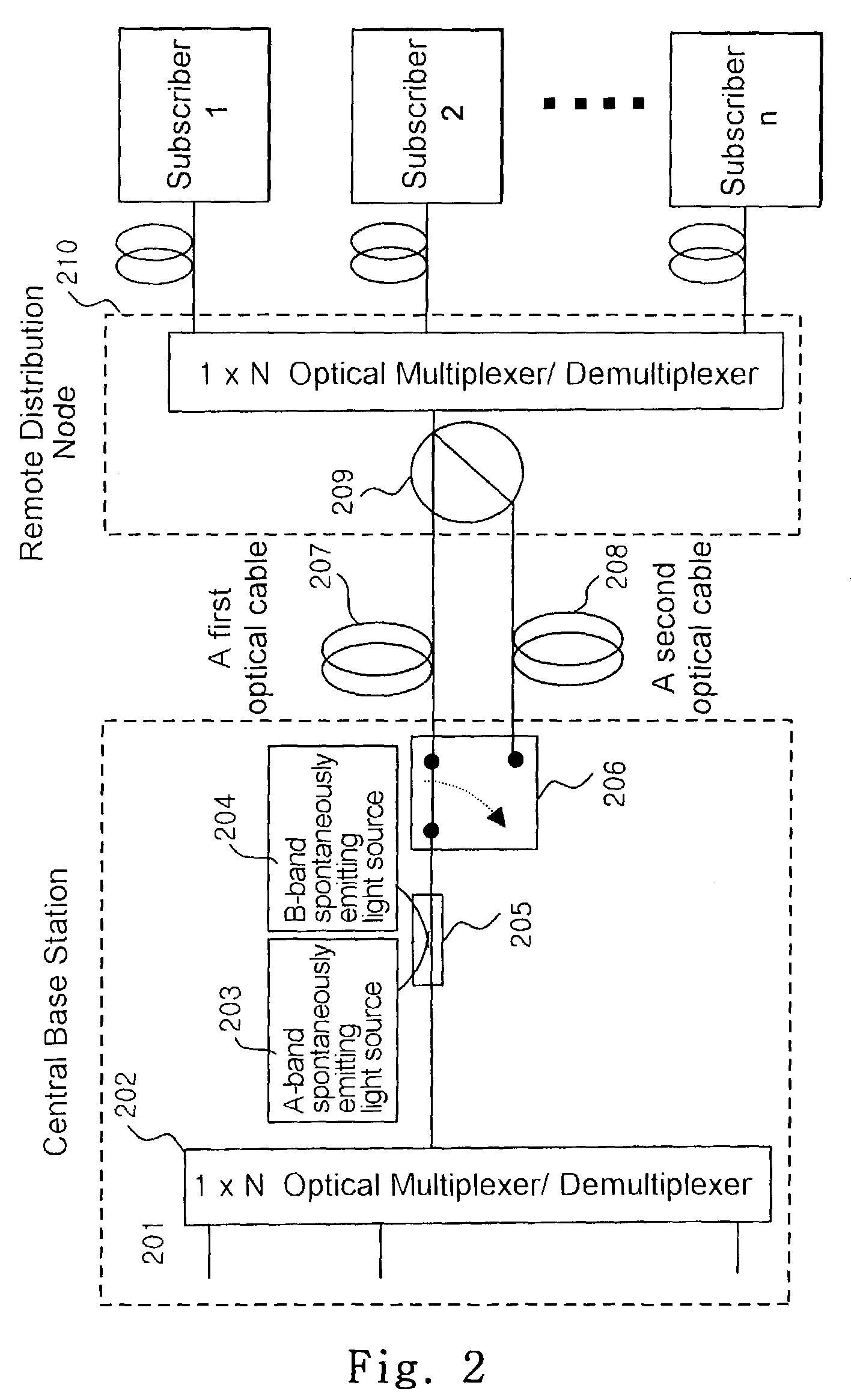
With this method, however, a optical loss, typically 3 dB, is additionally occurred due to the optical splitter (209) used at a remote distribution node.

Method used


Image

  • Method for decreasing and compensating the transmission loss at a wavelength-division-multiplexed passive optical network and an apparatus therefor
  • Method for decreasing and compensating the transmission loss at a wavelength-division-multiplexed passive optical network and an apparatus therefor
  • Method for decreasing and compensating the transmission loss at a wavelength-division-multiplexed passive optical network and an apparatus therefor

Examples


Embodiment Construction

[0027]Hereinafter, referring to appended drawings, the structures and operation principles of embodiments of the present invention are described in detail.

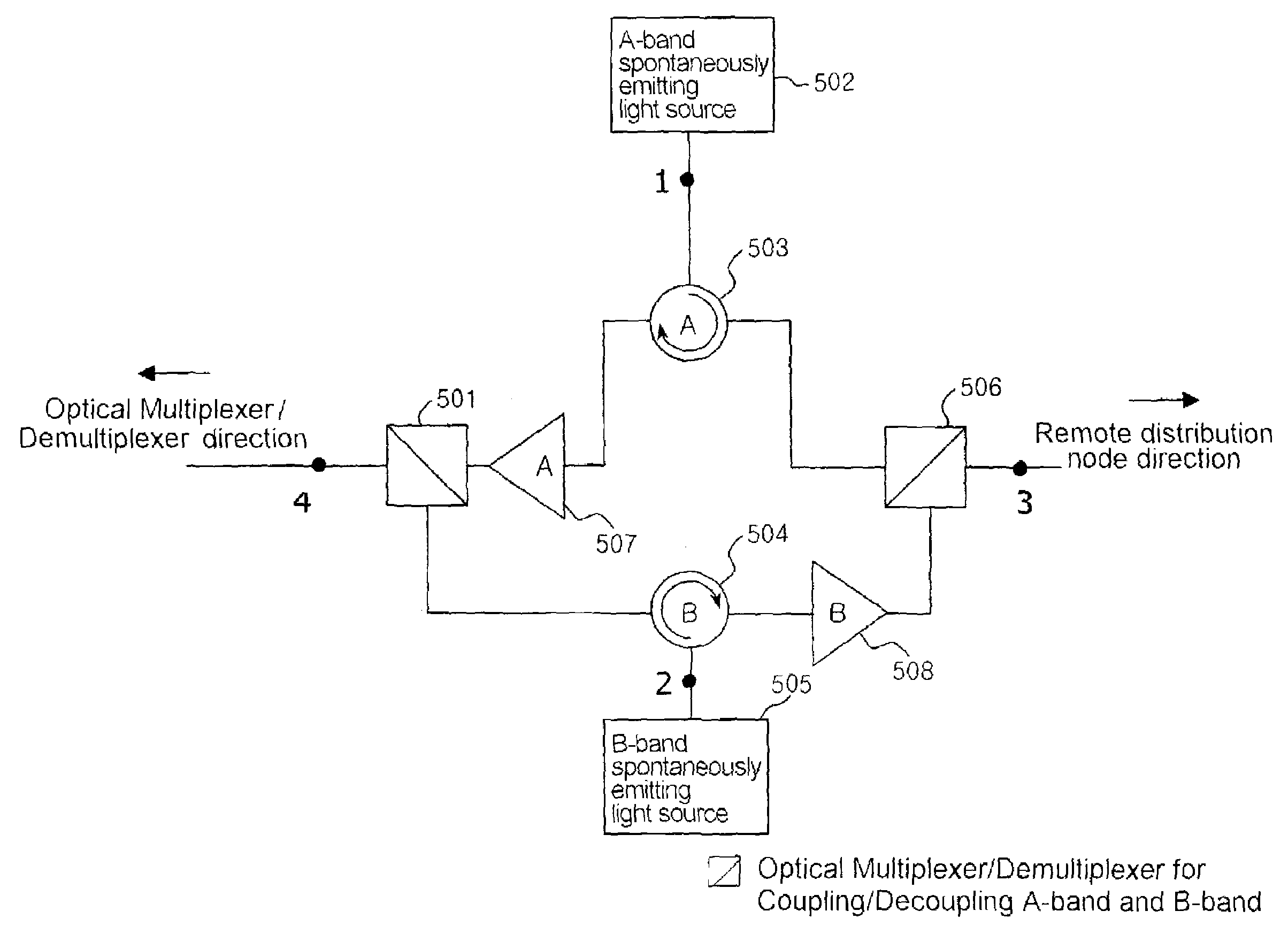
[0028]FIG. 3 is a view illustrating the operation characteristics of a 4-port optical path setting device in accordance with the present invention and its operating embodiment in a wavelength-division multiplexed passive optical network.

[0029]An A-band optical signal inputted through #1 port of the 4-port optical path setting device is outputted through #3 port. An A-band optical signal inputted through #3 port of the 4-port optical path setting device is outputted through #4 port. A B-band optical signal inputted through #2 port of the 4-port optical path setting device is outputted through #4 port. And a B-band optical signal inputted through #4 port of the 4-port optical path setting device is outputted through #3 port.

[0030]As described in FIG. 3, a 4-port optical path setting device of the present invention substitutes a opti...


PUM


Abstract

The present invention relates to a wavelength-division multiplexed passive optical network. In particular, it relates to a technology for minimizing the optical loss at a wavelength-division multiplexed passive optical network based on wavelength-locked light source Thereby it improves the transmission quality and increases the transmission distance.A 4-port optical path setting device of the present invention increases the amount of light injected into an optical transmitter and thereby improves the wavelength-locking characteristic of a light source. In addition, it can decrease the optical transmission loss in an optical transmission path, and by an optical amplifier being inserted therein; it can also compensate the optical loss in an optical transmission path.In the present invention, a 4-port optical path setting device having the characteristics described above and a method for fault recovery without an additional optical loss are presented.

Description

BACKGROUND OF THE INVENTION[0001]1. Field of the Invention[0002]The present invention relates to a wavelength-division multiplexed passive optical network. In particular, it relates to a technology for minimizing the optical loss at a wavelength-division multiplexed passive optical network based on wavelength-locked wavelength-division-multiplexed light sources. It improves the transmission quality and increases the transmission distance.[0003]2. Description of the Related Art[0004]A wavelength-division-multiplexed passive optical network includes a central office, subscribers and an optical distribution network. The optical distribution network connects between the subscribers and the central office without any element requiring the electrical power supply. The optical distribution network has an optical fiber cable and a remote distribution node such as wavelength-division multiplexer / demultiplexer. Wavelength-division multiplexed optical signals are transmitted through an optical...

Claims


Application Information

Patent Timeline
Patent Type & Authority Patents(United States)
IPC IPC(8): H04J14/02H04B10/032H04B10/25H04B10/27H04B10/272H04B10/293H04B10/297
CPCH04B10/032H04B10/2503H04B10/27H04B10/272H04J14/0297H04B10/2972H04J14/02H04B10/2939H04J14/0282H04B10/2589H04J14/0307H04B10/2581H04B10/2507
Inventor LEE, CHANG HEEOH, TAE WONCHU, KWANG UK
Owner KOREA ADVANCED INST OF SCI & TECH
Learn More