Remotely anchored tissue fixation device

a tissue fixation device and tissue technology, applied in the field of surgery, can solve the problems of increasing the risk of wound infection and wound dehiscence, the sophistication of manual suture placement in wounds has advanced relatively little, and the process is successful

Inactive Publication Date: 2007-02-06
OXFORD FINANCE +2
View PDF95 Cites 903 Cited by
  • Summary
  • Abstract
  • Description
  • Claims
  • Application Information

AI Technical Summary

Benefits of technology

[0020]The present invention is a device that allows the approximation of two regions of soft tissue during minimally invasive surgery while providing the surgeon a means to calibrate the degree of approximation necessary to achieve a specific result. In the preferred embodiment, one or more regions of edges are stabilized by a plurality of attachment points that extend from and are affixed to one or more supportive backings. The density, shape, length, and orientation of attachment points on the backing may be varied to suit the procedure, type of tissue being approximated, and / or area of the body involved. The flexibility of the backing is also variable and dependent on the materials used and dimensions of the backing. In function, the forces or tension placed upon the tissues by the inventive device are mirrored in the backing of the device. Said another way, the shape of the tines relay any forces to the backing of the device. The backing is generally in shear along its length. In the preferred embodiment, the device is biodegradable, and the attachment points optimally distribute tension over the contact area between the device and tissue and the backing is anchored at region remote from the site or sites of attachment with the anchoring and attachment regions connected by a bioabsorbable conduit.
[0023]In either case, the procedures may be accomplished by a variety of methods. One particularly useful tool may comprise a manipulatable handle having opposing grasping arms. The grasping arms may be used to secure and handle the device via the anchoring post. The tool may include a slidable block which may be angularly disposed relative to the handle so that the block may press down and secure a portion of the tissue to be lifted. The block is preferably disposed angularly such that the angle of the block is similar to the angle of the attachment points affixed to the device. Angling the block may allow the tissue to be optimally set against the attachment points and may provide the least resistance to piercing the tissue. Alternatively, the tool may omit the slidable block completely and the tissue may be set against the attachment points by other methods such as simply pressing against the tissue by hand.
[0027]Another variation includes a bone anchor or post joined to the supportive backing via a narrow extension member. The extension member may be flexible or solid. The extension member may also be adjustable in length. The extension member (or leash) may have particular mid-face or lower face applications. The adjustable leash may be made with multiple engagement holes defined along its length for adjustably engaging the backing along the length of the leash. The bone anchor may be inserted within a drilled hole located, e.g., in the infraorbital rim or medial zygomatic arch, and the backing may be positioned, while attached to the anchor, below the infraorbital rim of the midface. Once the tissue to be approximated has been affixed onto the backing, the distance between the backing and the anchor may be adjusted, i.e., shorted or lengthed, by pulling or pushing the connecting member through an adjustable latch defined on the backing. The latch is preferably configured to have a pawl or catch mechanism to allow the connecting member to be passed through the latch and selectively engaged when desired, thereby allowing for in vivo or ex vivo adjustment of the device to control the amount of tissue approximation.

Problems solved by technology

However, this process is successful only if the previous mechanical phase has proceeded normally.
Both of these circumstances increase the risk of wound infection and wound dehiscence.
Although the biomaterial composition of sutures has progressed considerably, the sophistication of manual suture placement in wounds has advanced relatively little since the original use of fabrics several thousand years ago to tie wound edges together.
Soft tissue is well known for its inability to hold tension.
Even when optimally placed, sutures gradually tear through soft tissue, producing gaps in wounds and possibly leading to the eventual failure or sub-optimization of wound healing.
Furthermore, since sutures require the implementation of high levels of tension to counteract the forces acting to separate tissues, they may strangulate the blood supply of the tissues through which they are placed, thus inhibiting the delivery of nutrients and oxygen necessary for healing at and near the site of tissue fixation and repair.
However, these devices are not useful in surgical or deeper wounds.
The devices minimally improve the biomechanics of wound closure, and do not adequately approximate the deeper layers of the closure, i.e. fascia or dermis.
However, these devices either work in conjunction with sutures, are made of materials that do not suggest biodegradability, or are designed in such a way as not to impart uniform tension on the closure, increasing the risk of wound separation and failure of wound healing.
Current orbital rim, craniofacial, and maxillofacial reconstructive procedures have a number of problems to overcome.
Failure to re-anchor the soft tissue results in undesirable sagging or drooping.
This conventional technique is undesirable for the reasons set forth above in connection with the use of sutures.

Method used


Image

  • Remotely anchored tissue fixation device
  • Remotely anchored tissue fixation device
  • Remotely anchored tissue fixation device

Examples


Embodiment Construction

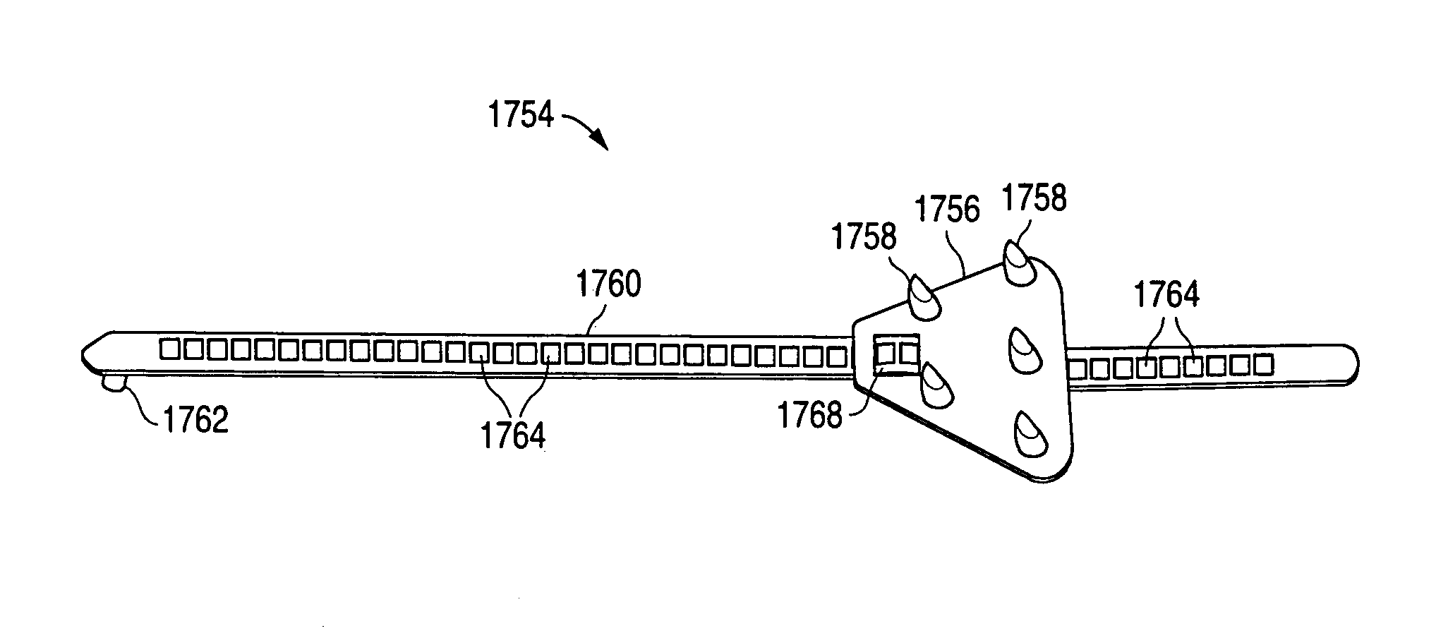
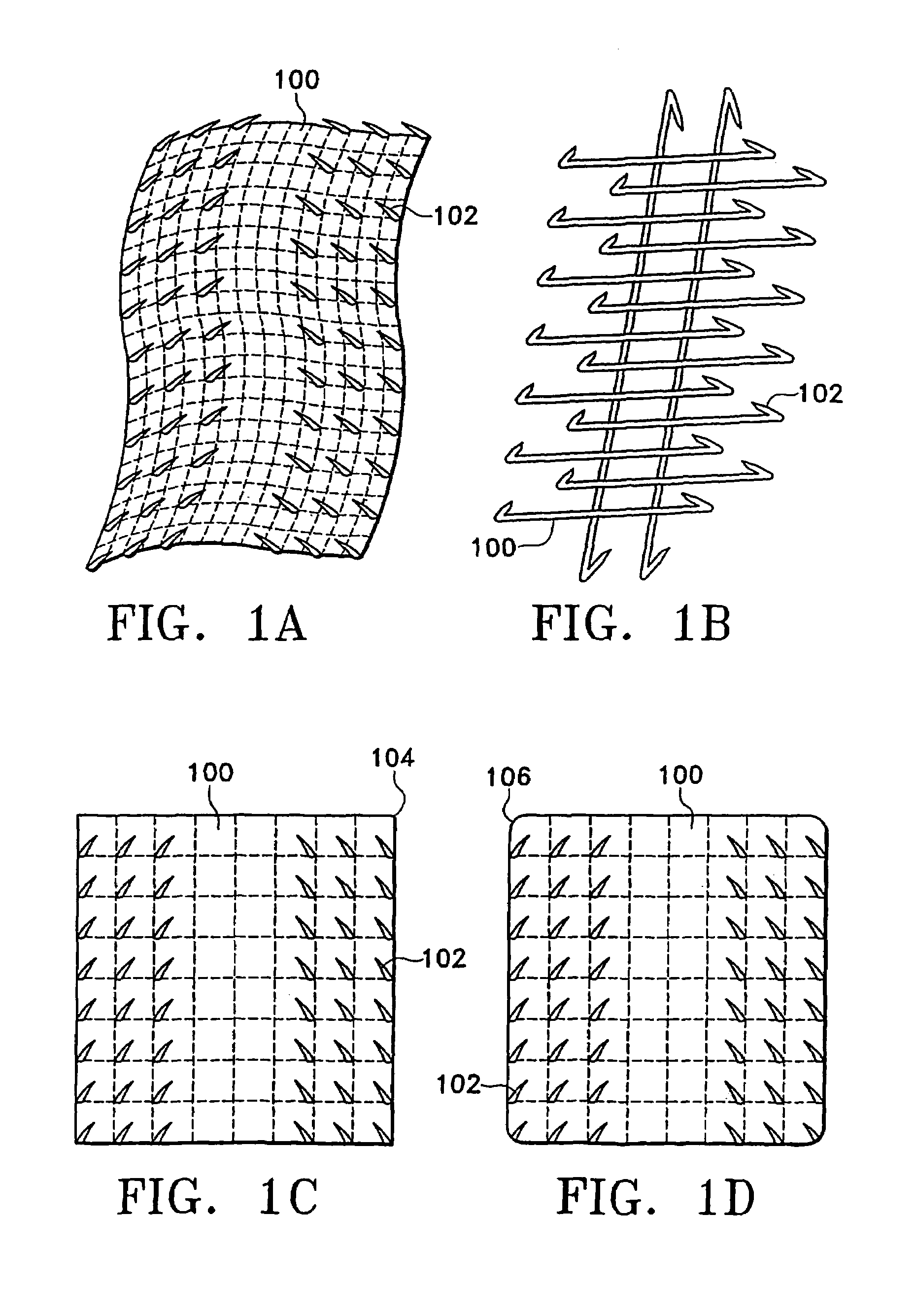
[0120]Our inventive device may be used when working with bone anchors or a variety of soft tissues. The device is of the general configurations shown in FIGS. 1A–1B and comprises a plurality of attachment points (102) emanating from and preferably affixed to a supportive backing (100) that is a generally a porous material that may have the structure of a mesh, net, or lattice. The degree of flexibility of the backing is determined by the material of construction, the shape and dimensions of the device, the type and properties of the approximated tissue, and the area of the body into which the device is placed. For example, a tightly curved or mobile part of the body, e.g., a joint, will require a more flexible backing, as would a tendon or nerve repair due to the amount of bending the device needs for the attachment. Also, depending on the type of material used, the thickness of the backing as well as its width and length may determine the flexibility of the device. Furthermore, the...


PUM

PropertyMeasurementUnit
diameteraaaaaaaaaa
incision lengthaaaaaaaaaa
diameteraaaaaaaaaa

Abstract

A tissue approximation device and processes for using the device, particularly in the mid-face region, are provided. The device is an implantable, biodegradable construct that has attachment points emanating from at least one supportive backing. The device also has a connecting member or leash which extends between the backing and an anchor which is attached to bone or soft tissue. Attachment to soft tissue is accomplished by a second backing having attachment points emanating from the backing and attachment to bone is accomplished by a post. The connecting member allows for repeated adjustments in length between the anchor and the backing in vivo or ex vivo until the desired amount of tissue approximation is achieved. The device improves the mechanical phase of wound healing and evenly distributes tension over the contact area between the device and tissue.

Description

CROSS-REFERENCE TO RELATED APPLICATIONS[0001]This is a continuation-in-part of U.S. patent application Ser. No. 09 / 816,641 filed Mar. 22, 2001, entitled “Multi-Point Tissue Tension Distribution Device, A Combined Orbital Rim Repair And Suspension Variation, And A Method Of Tissue Approximation Using The Device”, which is a continuation-in-part of U.S. patent application Ser. No. 09 / 788,118 filed Feb. 16, 2001, now U.S. Pat. No. 6,485,503, entitled “Multi-Point Tension Distribution System Device, A Brow And Face Lift Variation, And Method Of Tissue Approximation Using The Device”, which is a continuation-in-part of U.S. patent application Ser. No. 09 / 574,603, filed May 19, 2000, now U.S. Pat. No. 6,645,226, entitled “Multi-Point Tension Distribution System Device And Method Of Tissue Approximation Using That Device To Improve Wound Healing”, each of which is incorporated herein by reference in its entirety.FIELD OF THE INVENTION[0002]This invention is in the field of surgery. More pa...

Claims


Application Information

Patent Timeline
Patent Type & Authority Patents(United States)
IPC IPC(8): A61B17/08A61B17/00A61B17/04A61B17/064A61B17/11A61B17/56A61B17/58A61B19/00A61F2/00A61L31/00
CPCA61B17/064A61B17/08A61B17/11A61B19/24A61B2017/1107A61B17/085A61B17/1128A61B17/1146A61B2017/00004A61B2017/0496A61B2017/0641A61B2017/0647A61B2017/0648A61B2017/081A61B17/0643A61B90/02A61F2/0059A61F2/0063A61F2210/0004A61F2220/0016
Inventor MORRISS, JOHN H.JACOBS, DANIELELSON, ROBERT J.
Owner OXFORD FINANCE
Why Eureka
Try Eureka