[0010]The foregoing problems are solved and a technical advance is achieved in an illustrative cannula stent of the present invention wherein at least one longitudinally extending strut that laterally interconnects with other struts at respective ends thereof to form for example a T-shaped or W-shaped strut interconnection is selectively increased in width toward the interconnection to advantageously distribute potential strain experienced thereat during for example radial expansion of the stent and to further advantageously minimize, if not eliminate, fractures, cracks, or gaps at
high concentration areas of tensile strain at or near the strut interconnection. Such selective increase in strut width toward a strut interconnection can similarly and advantageously distribute tensile strain during other expansions and contractions of a cannula stent such as with pulsatile expansion and contraction. In particular, the cannula stent includes an elongated member having a passageway extending longitudinally therein and a wall of
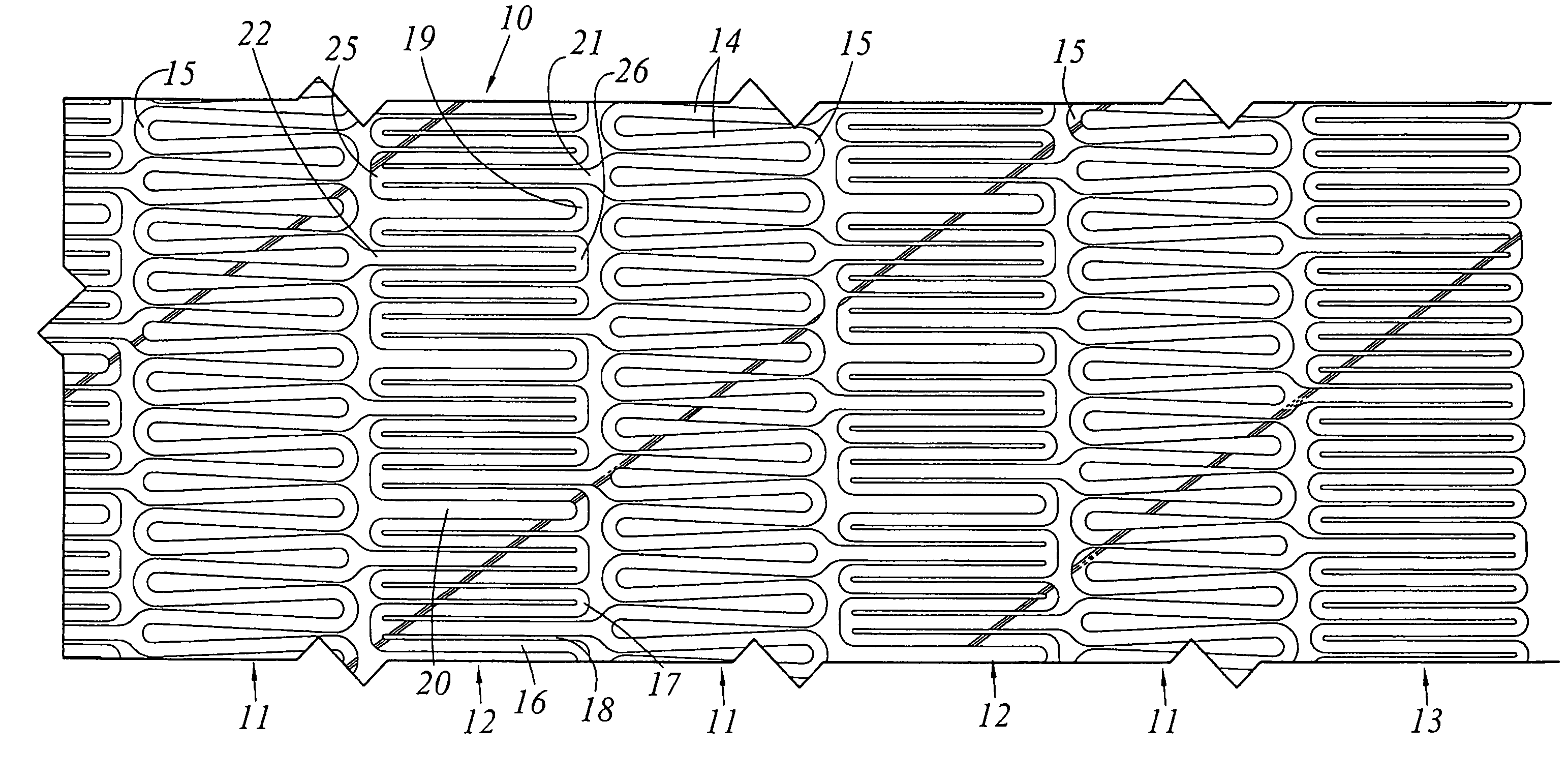
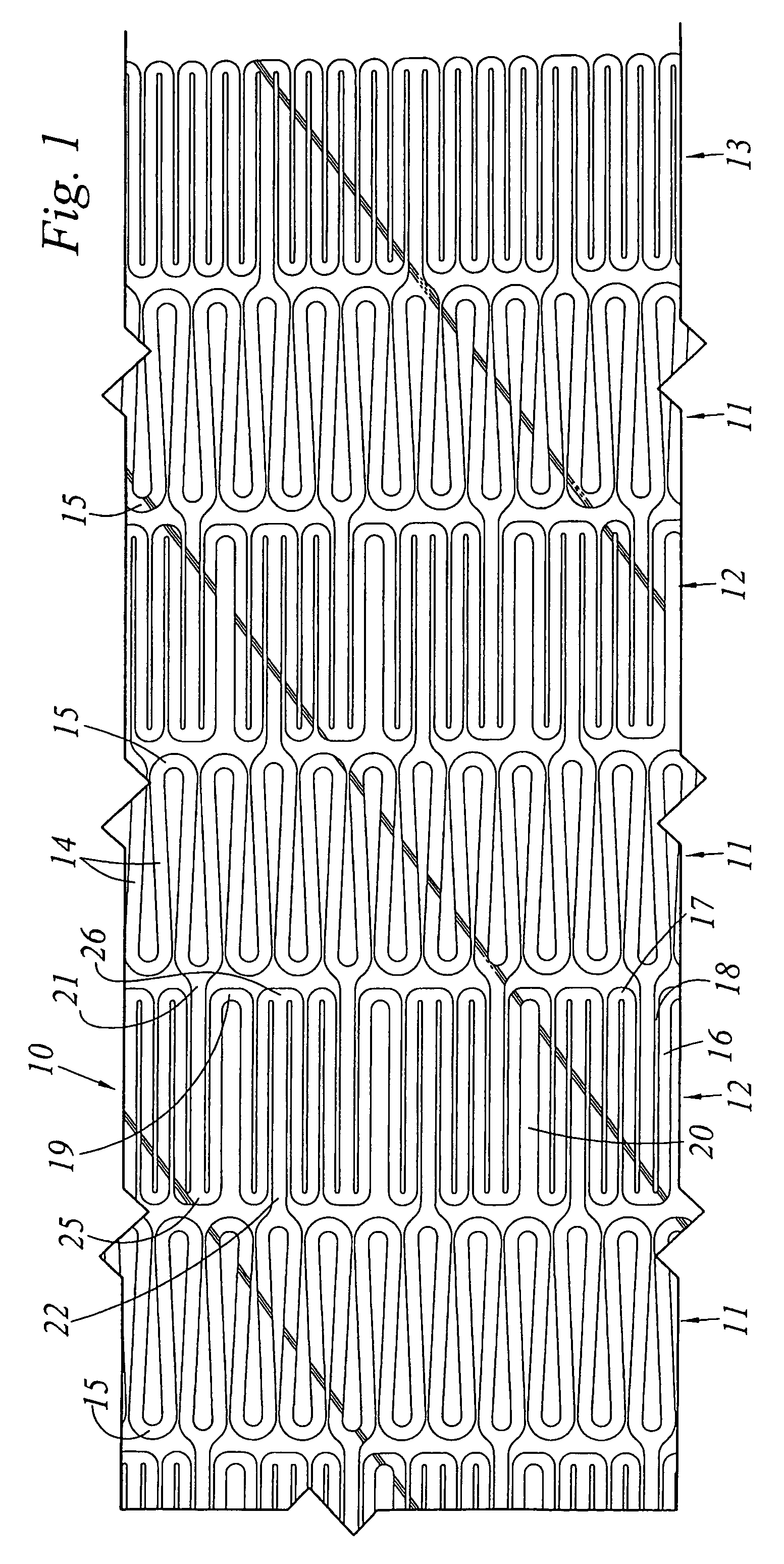
biocompatible material extending at least partially around the passageway. The wall has a plurality of struts extending longitudinally therein and plurality of elongated openings therethrough and interposed between the struts. First, second, and thirds ones of the struts are adjacent and have respective ends laterally interconnected at a strut interconnection. A first opening extends between the first and second struts and has a first opening end longitudinally adjacent the strut interconnection. A second opening extends between the second and third struts and has a second opening end also longitudinally adjacent the strut interconnection. The first strut has a selected width that increases along the strut toward the first opening end to advantageously distribute tensile strain along the strut and away from the first opening end during at least radial expansion of the stent. Thus, this advantageously lowers
high concentration levels of tensile strain about the strut ends and minimizes, if not eliminates, fractures, cracks, or gaps and the like during radial or other expansion and contraction of the stent.
[0011]Advantageously, the third strut of the cannula stent also has a selected width that increases along the strut toward the second opening end to likewise distribute tensile strain along the strut during at least radial expansion of the stent. This increase in the selected width of the struts toward the opening ends further advantageously minimizes, if not eliminates, undesirable fractures, cracks, or gaps created during radial or other expansion and contraction of the cannula stent at a
high concentration of tensile strain.
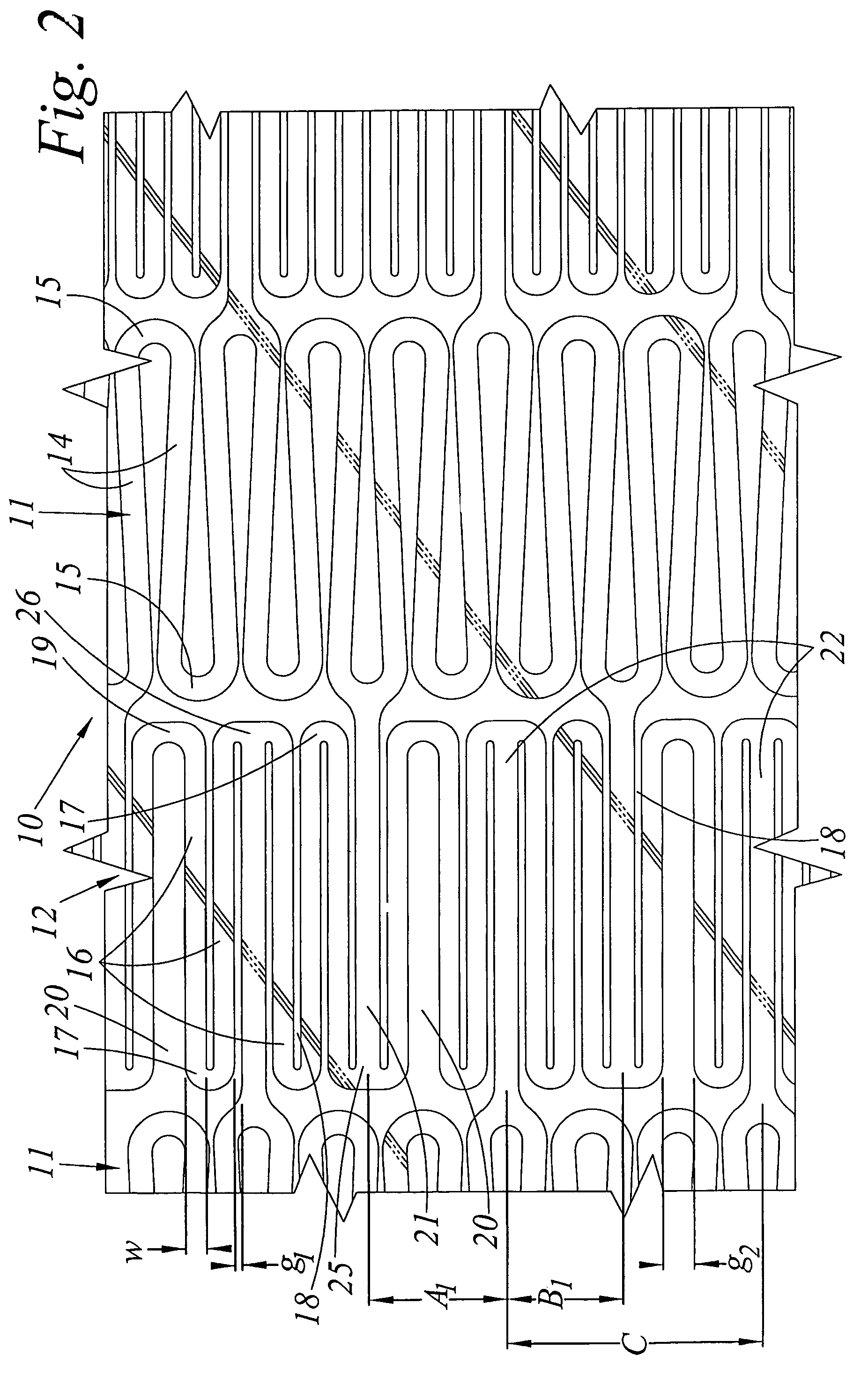
[0012]The increase of the selected width advantageously increases longitudinally along the strut toward the opening end adjacent the strut interconnection. This further advantageously distributes and lowers tensile strain created during radial and other expansion and contraction of the stent. The increase on either one or both of the first and third longitudinal struts extends at least partially along a length of the strut in a range from 10 to 30 percent of the length of the strut. Preferably, the increase in strut width occurs in a range of 12.5 to 25 percent of the length of the strut and, more preferably, in less then 20 percent of the length of the strut. This advantageously prevents undesirable high concentration of tensile strain from being distributed to or formed at other strut interconnections.
[0014]Another consideration to improve distribution and to lower concentrations of tensile strain particularly during pulsatile expansion and contraction is that the strut interconnection has an appropriate interconnection length that extends longitudinally from the first opening end to the longitudinally opposite edge of the interconnection across from the first opening end. This appropriate interconnection length is greater then the selected width of the strut, preferably the widest selected width of the strut, and is greater then the selected width of the strut in a range of 10 to 30 percent. Preferably, the interconnection length is greater then the selected width of the strut by 15 to 25 percent and, more preferably, when the interconnection length is greater then the selected width of the strut by about 20 percent. Selectively choosing the interconnection lengths of the strut interconnection to be equivalent from the first and second opening ends along with selectively increasing the selected width of the strut further advantageously distributes tensile strain during radial and pulsatile expansion and contraction of the stent.
[0015]To further minimize tensile strain and resulting fractures, cracks, or gaps, the elongated openings between adjacent struts are rounded about the opening ends and, more particularly, are at least partially elliptical about the opening ends. The inside
diameter width of the strut is more prone to fracturing or
cracking than the outside
diameter width of the strut and, in particular, about the opening ends. An at least partially elliptical opening end advantageously minimizes or narrows the difference between the inside and outside
diameter widths of the strut about the opening end. Thus, the elliptically shaped opening end is advantageously less susceptible to fracturing or
cracking than that of a semicircular opening end. In addition, the increase in strut width toward the opening ends can be curvilinear to further minimize fractures, cracks, or gaps.
Rounding or
smoothing the edges, ends, and sides of the struts and strut interconnections along with the increases in interconnection lengths and selected widths of the struts are combined to more evenly distribute tensile strain along the struts and away from the opening ends.
[0016]To yet further minimize tensile strain and resulting fractures, cracks, or gaps, the elongated opening between adjacent struts are rounded about the opening ends and, more particularly, are at least partially elliptical at the opening ends. A cannula stent is advantageously
cut with a
laser beam directed toward the axis of the cannula tube. As a result, the width of any strut varies from the outside diameter to that of the inside diameter of the cannula tube. A single cut opening is normally uniform in width due to the cylindrical width of the
laser beam. However, the width of a multiple
laser cut opening, like a strut, can also vary in width from the outside diameter to the inside diameter of the cannula tube. The strut has a outside diameter selected width and an inside diameter selected width that is less than the outside diameter selected width of the strut. In other words, the selected width of the strut along the inside diameter of the cannula tube is less than the selected width along the outside diameter of the cannula tube. As a result, the cross-sectional area of the longitudinal strut is asymmetrical and fractures, cracks, or gaps will more often appear at a strut edge along the inside diameter of the tube during radial or other expansion of the strut during manufacture. To advantageously minimize, if not eliminate, fractures, cracks, or gaps at the inside diameter of a longitudinal strut, the elongated opening adjacent to the strut is formed to have an at least partially elliptical opening thereabout. As a result, the ratio of the inside diameter selected width to that of the outside diameter selected width is increased, and the cross-sectional area of the longitudinal strut becomes more symmetrical. This advantageously minimizes the concentration of tensile strain during expansion and / or contraction of the stent during manufacture and in the patient. This elliptically shaped opening also advantageously decreases the ratio of the inside diameter to the outside diameter selected width of the elongated opening, thus further contributing to the increase in the inside diameter strut width about the elongated end at a strut interconnection and making the cross-sectional area of the longitudinal strut even more symmetrical.

