
Separator for fuel cell and manufacturing method for the same

a technology of separator and fuel cell, which is applied in the field of separator for fuel cell, can solve the problems of deteriorating gas-impermeability of separator, increasing manufacturing cost, and long time required, and achieves the effect of sufficient gas-impermeability

Inactive Publication Date: 2007-02-06
TOYOTA JIDOSHA KK
View PDF26 Cites 4 Cited by
  • Summary
  • Abstract
  • Description
  • Claims
  • Application Information

AI Technical Summary

Benefits of technology

[0008]It is an object of the present invention to solve the aforementioned problem, and to provide a separator for a fuel cell having sufficient gas-impermeability using a simple method.
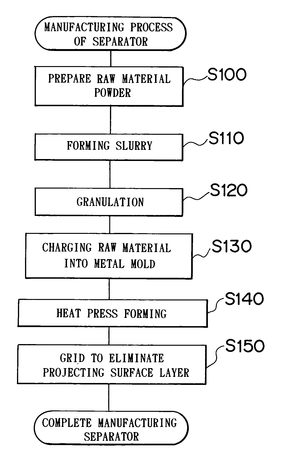
[0010]According to the method of manufacturing a separator for a fuel cell, as the epoxy resin is used in addition to the phenolic resin as the binder, no gas is generated by the binder during thermosetting process thereof in the heat resulting from the forming step. This may prevent swelling of the separator obtained by the heat-press forming, thus providing a separator exhibiting sufficient gas-impermeability.
[0013]Accordingly the hydroxyl group of the phenolic resin in the binder is allowed to react sufficiently with the epoxy group (three members contained) in the epoxy resin, and gas generated from the phenolic resin during heating can be suppressed. Further, as the amount of epoxy resin is not excessively increased as compared with the amount of phenolic resin, thereby preventing elongation of a time required to thermoset the binder owing to excessive increase in the amount of the epoxy resin.
[0015]The scaly natural graphite particles exhibit a predetermined binding capability during press forming. Therefore the amount of the binder added to the raw material can be reduced by using carbon powder formed of scaly natural graphite particles. Since the thermosetting resin as the binder has no conductivity, the conductivity of the separator can be improved by reducing the amount of binder. If the amount of binder added to the raw material exceeds the predetermined amount, the strength of the resultant separator is likely to be deteriorated at a temperature equal to or higher than the temperature corresponding to the one at which the fuel cell is operated. However, the strength of the separator can be sufficiently secured by reducing the amount of the binder added to the raw material.
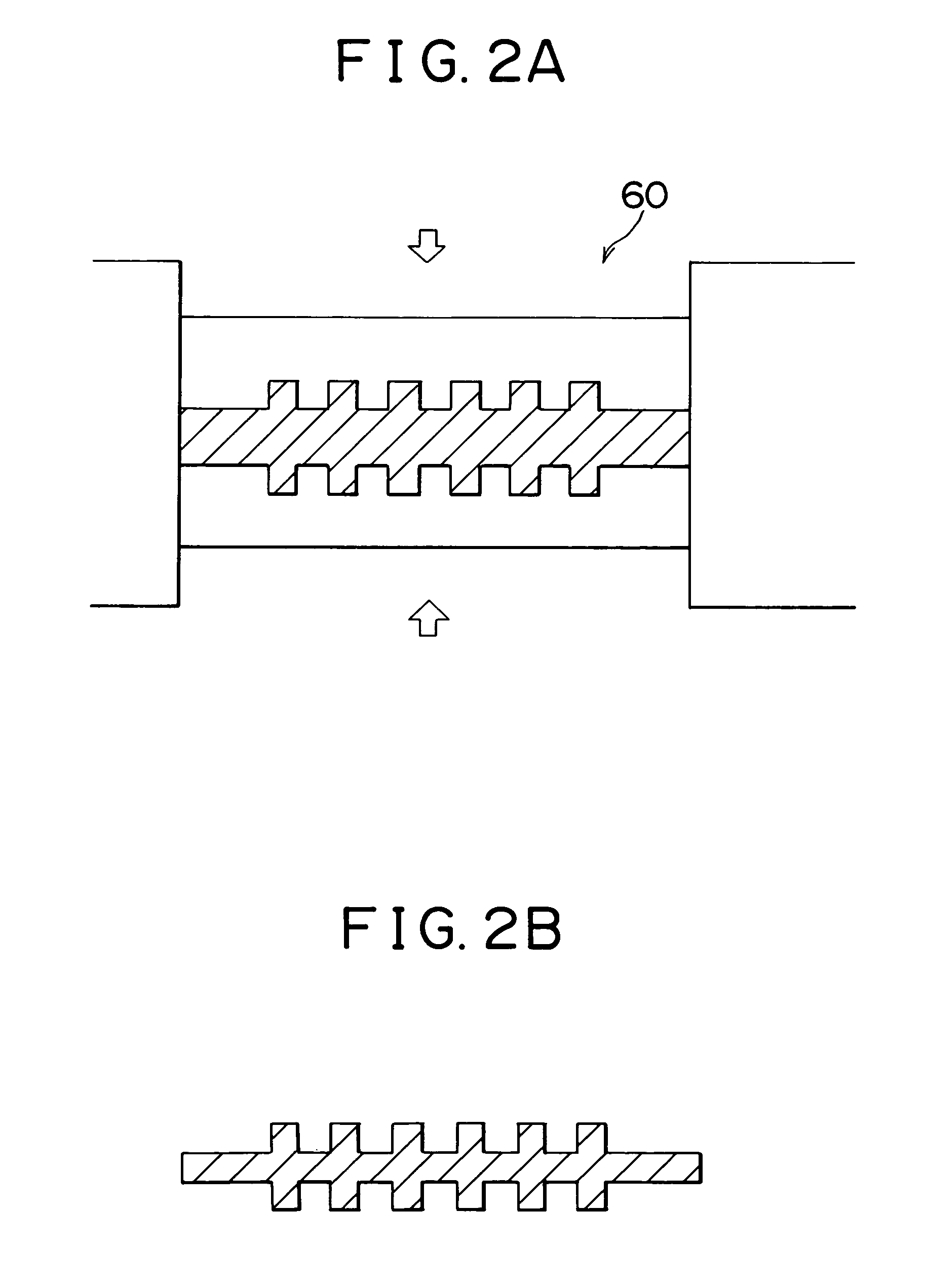
[0016]Additionally it is preferable to provide the step where one of surfaces of the separator in contact with the fuel cell is eliminated by grinding when it is incorporated in the fuel cell.
[0017]The aforementioned structure makes it possible to eliminate the binder layer formed on the separator surface and a mold-separating agent adhered to the separator surface. That is, when subjecting the carbon and the raw material containing a binder formed of a thermosetting resin to heat press forming, the binder melted during the forming process is blurred out to form the binder layer on the separator surface. Further, the mold-separating agent is applied onto the metal mold for press forming so as to enhance the mold-separation to draw the separator from the metal mold (to make it easier to draw the separator from the metal mold). At least a portion of the mold-separating agent will adhere to the surface of the separator drawn from the metal mold. The binder layer or the mold-separating agent adhered onto the separator surface has no conductivity, thus allowing improvement of the conductivity of the separator through grinding treatment.

Problems solved by technology

This may elongate the time required for manufacturing and further complicate the manufacturing process, resulting in increased manufacturing cost.
Further, phenolic resin added to the carbon powder as the binder generates water during the baking step, which forms bubbles in the carbon members that have been baked.
As a result, the gas-impermeability of the separator is deteriorated.
This may further complicate the manufacturing process.
Accordingly bubbles are formed in the manufactured separator, resulting in insufficient gas-impermeability of the separator.

Method used


Image

  • Separator for fuel cell and manufacturing method for the same
  • Separator for fuel cell and manufacturing method for the same
  • Separator for fuel cell and manufacturing method for the same

Examples


Embodiment Construction

[0029]An embodiment of the present invention will be explained hereinafter.

[0030]A fuel cell having a separator manufactured using a method of manufacturing a separator according to the present invention has a stack structure in which a plurality of unit cells are stacked. FIG. 3 is a schematic view of a unit cell 28 constituting the fuel cell. FIG. 4 is an exploded perspective view showing a structure of the unit cell 28. FIG. 5 is a perspective view showing an appearance of a stack structure 14 formed by stacking the unit cells 28.

[0031]The fuel cell of the present embodiment is of a solid polymer type. The solid polymer type fuel cell includes, as an electrolytic layer, a membrane formed of solid polymer exhibiting excellent conductivity in a wet state. The fuel cell receives, at its anode side, fuel gas containing hydrogen, and receives, at its cathode side, oxide gas containing oxygen, such that the following electrochemical reaction takes place:

H2→2H++2e−  (1)

(½)O2+2H++2e−→H2O...


PUM

PropertyMeasurementUnit
particle size distributionaaaaaaaaaa
temperatureaaaaaaaaaa

Abstract

A separator for a fuel cell is manufactured by preparing a raw material powder, uniformly mixing the prepared raw material to be formed into a slurry, and charging the raw material powder derived from granulation into a metal mold for heat press forming. The raw material is obtained by adding to carbon powder a binder containing a mixture of phenolic resin and epoxy resin. Therefore the heat press forming step does not cause the binder to generate gas, thus allowing manufacturing of a separator exhibiting sufficient gas-impermeability.

Description

INCORPORATION BY REFERENCE[0001]The disclosure of Japanese Patent Application No. HEI 10-22752 filed on Jan. 19, 1998 including the specification, drawings and abstract is incorporated herein by reference in its entirety.BACKGROUND OF THE INVENTION[0002]1. Field of the Invention[0003]The present invention relates to a separator for a fuel cell and a method of manufacturing the separator. More specifically, in a fuel cell formed of a plurality of stacked unit cells, the present invention relates to a separator disposed between adjacent unit cells for forming a fuel gas passage and an oxide gas passage, by which fuel gas and oxide gas can be separated. The present invention further relates to a method of manufacturing the separator.[0004]2. Description of the Related Art[0005]As a method of a separator for a fuel cell, there is a known method described in Japanese Patent Application Laid-open No. HEI 8-222241 in which phenolic resin is added as a binder to carbon powder as a raw mater...

Claims


Application Information

Patent Timeline
Patent Type & Authority Patents(United States)
IPC IPC(8): H01M8/02B29B9/12B29C43/00C04B26/14
CPCB29B9/12B29C43/003H01M8/0213C04B26/14B29C43/006C04B14/024C04B24/302C04B40/00C04B40/0082C04B41/53Y02E60/50C04B2111/00853B29K2707/04B29K2063/00Y02P70/50
Inventor MIZUNO, SEIJI
Owner TOYOTA JIDOSHA KK
Learn More