Extreme ultra violet light source device

a light source device and ultra-violet technology, applied in the field oflp, can solve the problems of inability to obtain uniform droplets at uniform intervals, inability to generate uniform droplets, and no mechanism for forming droplets in consideration of amplitude and frequency, etc., to achieve efficient and stable generation, low price, and wide range of performance

Active Publication Date: 2007-02-06
GIGAPHOTON
View PDF5 Cites 28 Cited by
  • Summary
  • Abstract
  • Description
  • Claims
  • Application Information

AI Technical Summary

Benefits of technology

[0020]According to the present invention, the voltage generator is feedback controlled while the amplitude of the voltage between the terminals of the vibrator or the amount of the displacement (vibration amplitude) of the injection nozzle or the vibrator is monitored such that the amplitude falls within a predetermined range, and therefore, the injection nozzle can be vibrated with an appropriate amplitude according to the vibration frequency. Thereby, uniform droplets can be formed regardless of the vibration frequency, and EUV light can be generated efficiently and stably in the LPP EUV light source device. Further, since various droplet formation conditions are easily accommodated, devices having a wide range of performance can be provided at low prices. Furthermore, since the defects such as breakage and failure of the vibrator can be promptly detected by directly measuring the voltage between terminals of the vibrator, the vibrator amplitude or the injection nozzle amplitude, the reliability of the LPP EUV light source device can be improved.

Problems solved by technology

However, no mechanism has been disclosed for forming droplets in consideration of amplitude and frequency of the vibrator.
Accordingly, there has been a problem that droplets in desired sizes at uniform intervals can not be obtained.
Further, excessive injection nozzle vibration due to resonance is also generated around the resonant frequency band of the entire droplet injection nozzle including the vibrator, and therefore, the generation of uniform droplets is inhibited.

Method used


Image

  • Extreme ultra violet light source device
  • Extreme ultra violet light source device
  • Extreme ultra violet light source device

Examples


first embodiment

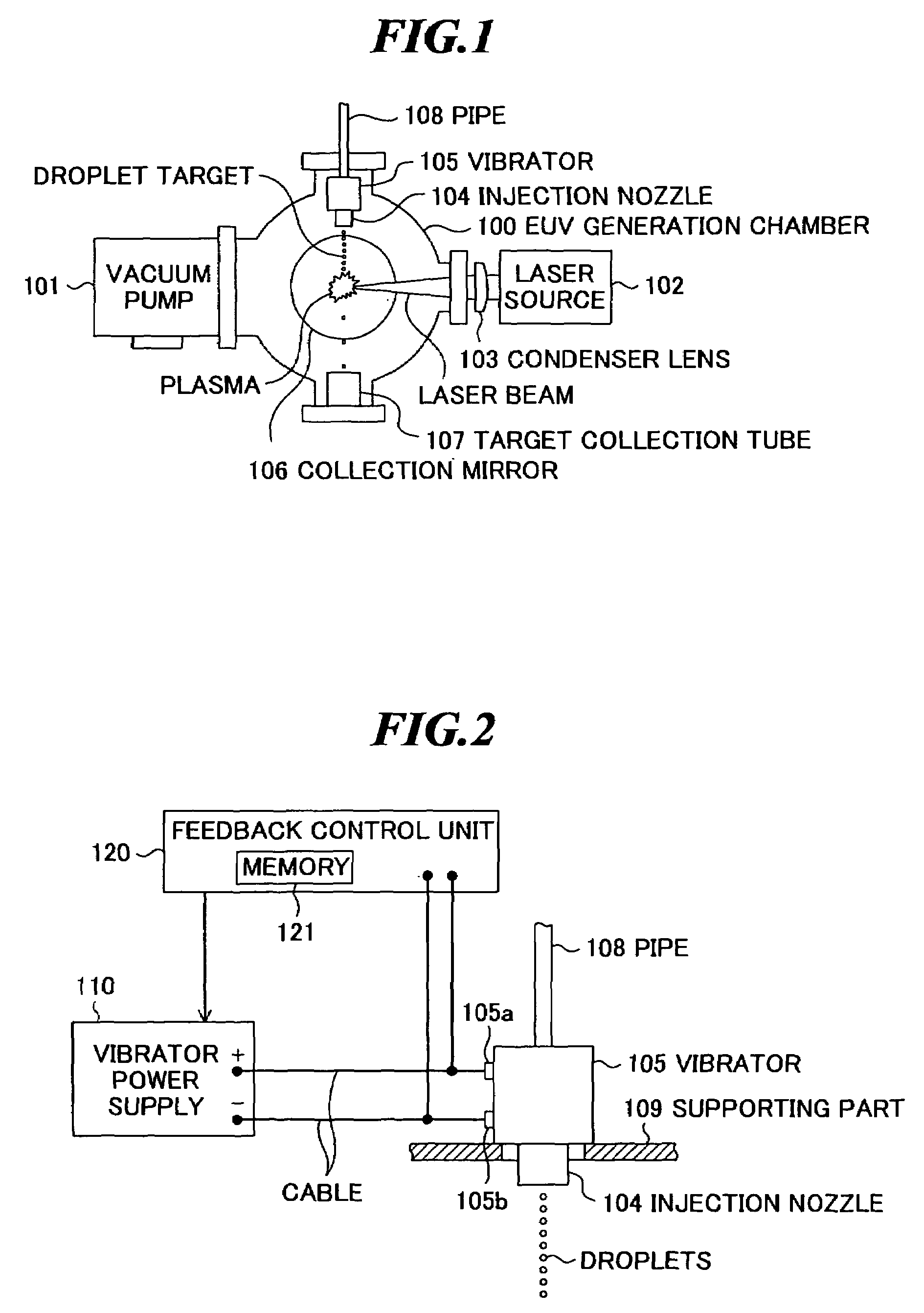
[0036]FIG. 2 is a schematic diagram showing a part of the LPP extreme ultra violet light source device according to the present invention, and shows the constitution of the injection nozzle 104 and vibrator 105 as shown in FIG. 1 in detail.

[0037]As shown in FIG. 2, the injection nozzle 104 is provided with a pipe 108 for supplying the target material to the injection nozzle 104. Further, the vibrator 105 is supported by a supporting part 109 fixed to the EUV generation chamber 100 (FIG. 1). The vibrator 105 is provided with two terminals 105a and 105b, and a vibrator power supply (voltage generator) 110 for generating a drive signal having a predetermined frequency to supply a voltage of the drive signal to the vibrator is connected to these terminals 105a and 105b via a cable. Furthermore, a feedback control unit 120 for feedback controlling the output voltage of the vibrator power supply 110 is provided to the vibrator power supply 110.

[0038]In the embodiment, a liquid target mate...

second embodiment

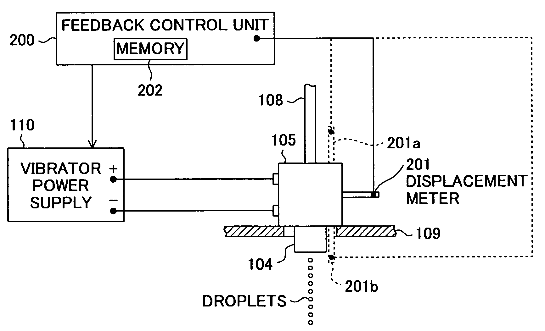
[0050]FIG. 4 is a schematic diagram showing a part of the LPP extreme ultra violet light source device according to the present invention. This LPPEUV light source device has a feedback control unit 200 in place of the feedback control unit 120 shown in FIG. 2, and further has at least one contact-type displacement meter (displacement gage) 201 as a measuring unit attached to the vibrator 105. Other constitution is the same as that of the LPP EUV light source device shown in FIGS. 1 and 2.

[0051]The displacement meter 201 is provided for measuring the amount of displacement of the vibrator 105. Further, the feedback control unit 200 feedback controls the output voltage of the vibrator power supply 110 based on the amount of displacement measured by the displacement meter 201 such that the vibrator 105 vibrates with desired amplitude (amplitude in a range in which uniform droplets can be formed). For example, the feedback control unit 200 has a nonvolatile memory 202 in which a databa...

third embodiment

[0056]FIG. 5 is a schematic diagram showing a part of the LPP extreme ultra violet light source device according to the present invention. This LPP EUV light source device has a feedback control unit 300 in place of the feedback control unit 120 shown in FIG. 2, and further has at least one contact-type displacement meter 301 as a measuring unit attached to the injection nozzle 104. Other constitution is the same as that of the LPP EUV light source device shown in FIGS. 1 and 2.

[0057]The displacement meter 301 is provided for measuring the amount of displacement of the injection nozzle 104. Further, the feedback control unit 300 feedback controls the output voltage of the vibrator power supply 110 based on the amount of displacement measured by the displacement meter 301 such that the injection nozzle 104 vibrates with desired amplitude (amplitude in a range in which uniform droplets can be formed). For example, the feedback control unit 300 has a nonvolatile memory 302 in which a d...


PUM


Abstract

An LPP EUV light source device for forming a uniform droplet target regardless of a frequency of a drive signal applied to a vibrator. The LPP EUV light source device includes: a chamber in which the extreme ultra violet light is generated; an injection nozzle that injects a target material into the chamber; a vibrator that has two terminals and vibrates to provide vibration to the injection nozzle when a drive signal is applied between the two terminals via a cable; a voltage generator that generates the drive signal; a controller that monitors a voltage between the two terminals of the vibrator and feedback controls the voltage generator such that an amplitude of the monitored voltage falls within a predetermined range; and a laser source that generates a laser beam to be irradiated to the target material injected from the injection nozzle.

Description

BACKGROUND OF THE INVENTION[0001]1. Field of the Invention[0002]The present invention relates to an LPP (laser produced plasma) extreme ultra violet (EUV) light source device for generating extreme ultra violet light to be used for exposing semiconductor wafers or the like.[0003]2. Description of a Related Art[0004]As semiconductor processes become finer, the photolithography has been making rapid progress to finer fabrication, and, in the next generation, microfabrication of 100 nm to 70 nm, further, microfabrication of 50 nm or less will be required. For example, in order to fulfill the requirement for microfabrication of 50 nm or less, the development of exposure equipment with a combination of an EUV light source of about 13 nm in wavelength and a reduced projection cataoptric system is expected.[0005]As the EUV light source, there are three kinds of an LPP (laser produced plasma) type using plasma generated by irradiating a laser beam to a target, a DPP (discharge produced plas...

Claims


Application Information

Patent Timeline
Patent Type & Authority Patents(United States)
IPC IPC(8): G01J1/00
CPCH05G2/003H05G2/005H05G2/008
Inventor NAKANO, MASAKI
Owner GIGAPHOTON
Why Eureka
Try Eureka