Apparatus for optically rotating microscopic objects

Inactive Publication Date: 2007-02-06
ST ANDREWS UNIV OF UNIV COURT OF THE
View PDF0 Cites 14 Cited by
  • Summary
  • Abstract
  • Description
  • Claims
  • Application Information

AI Technical Summary

Benefits of technology

[0025]The shift in frequency between the two beam components means that when they are recombined and interfere, the resulting pattern rotates with the frequency differen

Problems solved by technology

However, conventional optical tweezers provide little or no effective control over the orientation of the microscopic particles which they manipulate.
This in turn restricts the range of particles this method can be applied to and also further limits this technique in that heating from this absorption could damage the rotating particle.
Furthermore,

Method used


Image

  • Apparatus for optically rotating microscopic objects
  • Apparatus for optically rotating microscopic objects
  • Apparatus for optically rotating microscopic objects

Examples


Embodiment Construction

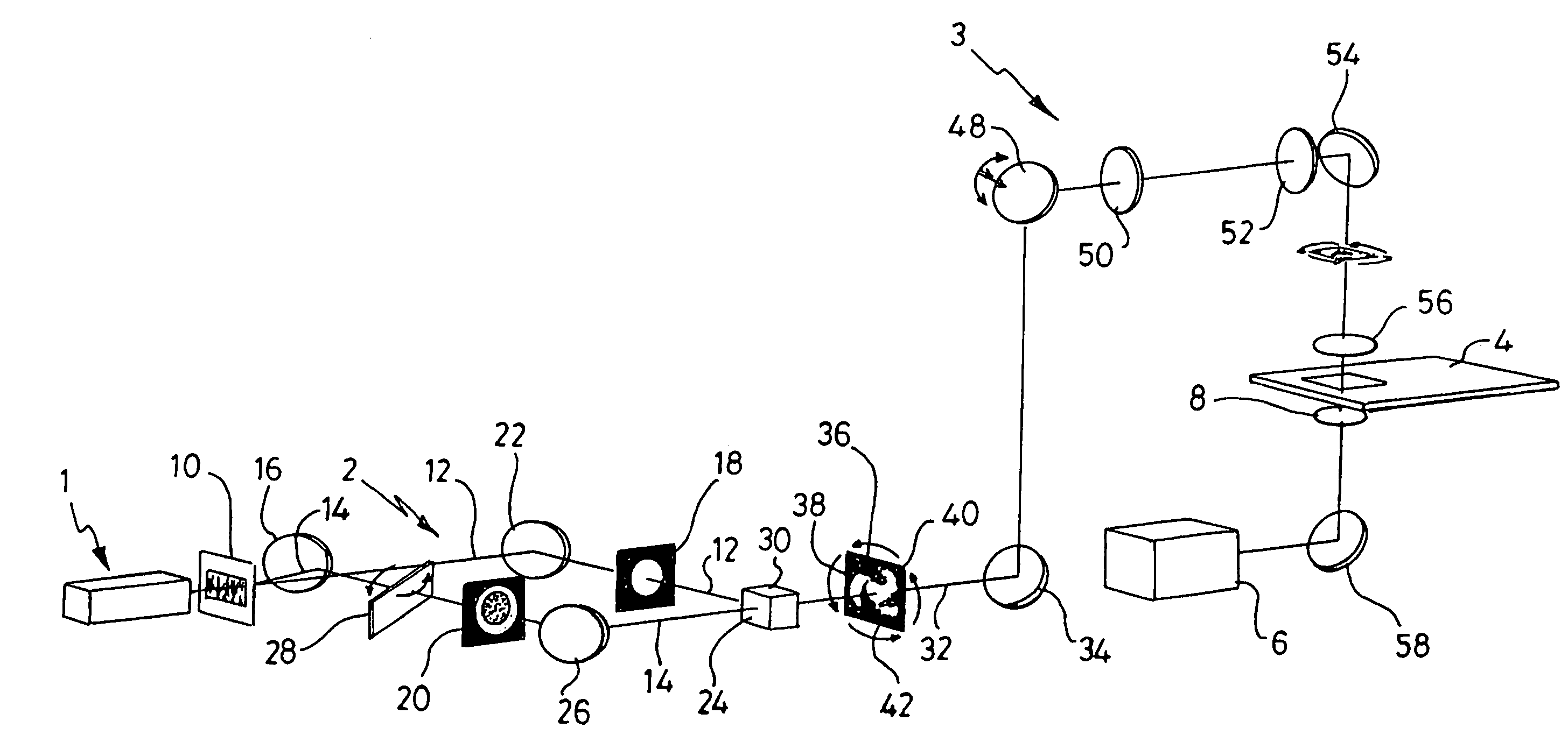
[0044]With reference to FIG. 1, an Nd=glass laser 1 of power 1W at 1064 nm faces an interferometer 2, the output of which passes to an optical tweezer assembly 3. The assembly 3 includes a microscope stage and sample cell holder 4 in which the object to be rotated / manipulated is retained. A camera 6 is used to obtain an image, via a microscope objective 8, of the sample cell and hence the object therein.

[0045]The interferometer 2 comprises a beam splitter in the form of a hologram element 10 that splits the beam into two components. One of those components is a plane wave component 12 which passes straight through the hologram element 10 substantially undeflected, and which is in the form of a solid beam. The second component, referenced 14 is deflected to one side of the component 12 and onto a mirror 16 which is positioned clear of the path of the component 12, and which is so angled as to direct the component 14 in a direction perpendicular to that of the component 12. The hologr...


PUM


Abstract

Apparatus for and a method of rotating microscopic objects uses a beam of electromagnetic radiation. A microscopic, non-circularly symmetric distribution of electro-magnetic radiation is projected on to a region containing an object to be rotated so as to cause photons in the beam to refract around the objects. Rotating means then rotate that distribution and so rotate the objects. The distribution may be formed on the interference pattern between a beam having a Laguerre-Gaussian wave fronts and either a plane wave or a further Laguerre-Gaussian beam of opposite helicity.

Description

FIELD OF THE INVENTION[0001]This invention relates to apparatus for rotating microscopic objects, and particularly to apparatus which uses a beam of electromagnetic radiation to that end. The invention also relates to a method of rotating a microscopic object using electromagnetic radiation.BACKGROUND TO THE INVENTION[0002]The use of optical forces to trap and manipulate micron size particles was pioneered by A. Ashkin over ten years ago. [See A. Ashkin, J. M. Dziedzic, J. E. Bjorkholm and S. Chu, Opt. Lett., 11,288 (1986)]. He showed that a single, tightly focused laser beam could be used to hold a microscopic particle in three dimensions near the focus of the beam. Apparatus using a beam in this way provides a powerful non-invasive technique for manipulating microscopic particles, and is generally known as “optical tweezers”.[0003]Optical tweezers have firmly established themselves as powerful tools, especially in the field of biology where they have enabled a range of studies to ...

Claims


Application Information

Patent Timeline
IPC IPC(8): G01B9/02G21K1/00H05H3/04
CPCH05H3/04G21K1/006
Inventor DHOLAKIA, KISHANMACDONALD, MICHAEL PETERARLT, JOCHEN
Owner ST ANDREWS UNIV OF UNIV COURT OF THE
Why Eureka
Try Eureka