Process of making a non-corrosive GMR slider for proximity recording

a proximity recording and slider technology, applied in the field of magnetically resistive disk drive head, can solve the problems of large amount of substrate and transducer wear, high cost, and high cost of proximity recording sliders made using inductive transducer technology, so as to minimize current spiking to the disk and minimize the height of the slider

Inactive Publication Date: 2007-02-13
WESTERN DIGITAL TECH INC
View PDF30 Cites 41 Cited by
  • Summary
  • Abstract
  • Description
  • Claims
  • Application Information

AI Technical Summary

Benefits of technology

[0017]An advantage of the present invention is that it does not rely on drive chemical filters and residual disc lubricant to protect the transducer.
[0018]Another advantage of the invention is the fly height of the slider can be minimized without risking damage to the copper element by corrosion.
[0019]And another advantage of the invention is current spiking to t

Problems solved by technology

At such close distances, the slightest surface irregularity can cause the ABS to contact the disk surface at least briefly.
Typical proximity recording sliders made using inductive transducer technology are subjected to large amounts of substrate and transducer wear during the initial hours of the drive operational life.
Currently, fly heights of GMR heads have reaching a point where some level of interference is required, and similar levels of wear on some heads will be expected.
To reduce wear on the sensitive transducer elements, a protective coating, typically of some very hard substance such as Diamond-Like Carbon (DLC) is used, but again, by interposing this protective layer, the sepa

Method used


Image

  • Process of making a non-corrosive GMR slider for proximity recording
  • Process of making a non-corrosive GMR slider for proximity recording
  • Process of making a non-corrosive GMR slider for proximity recording

Examples


Embodiment Construction

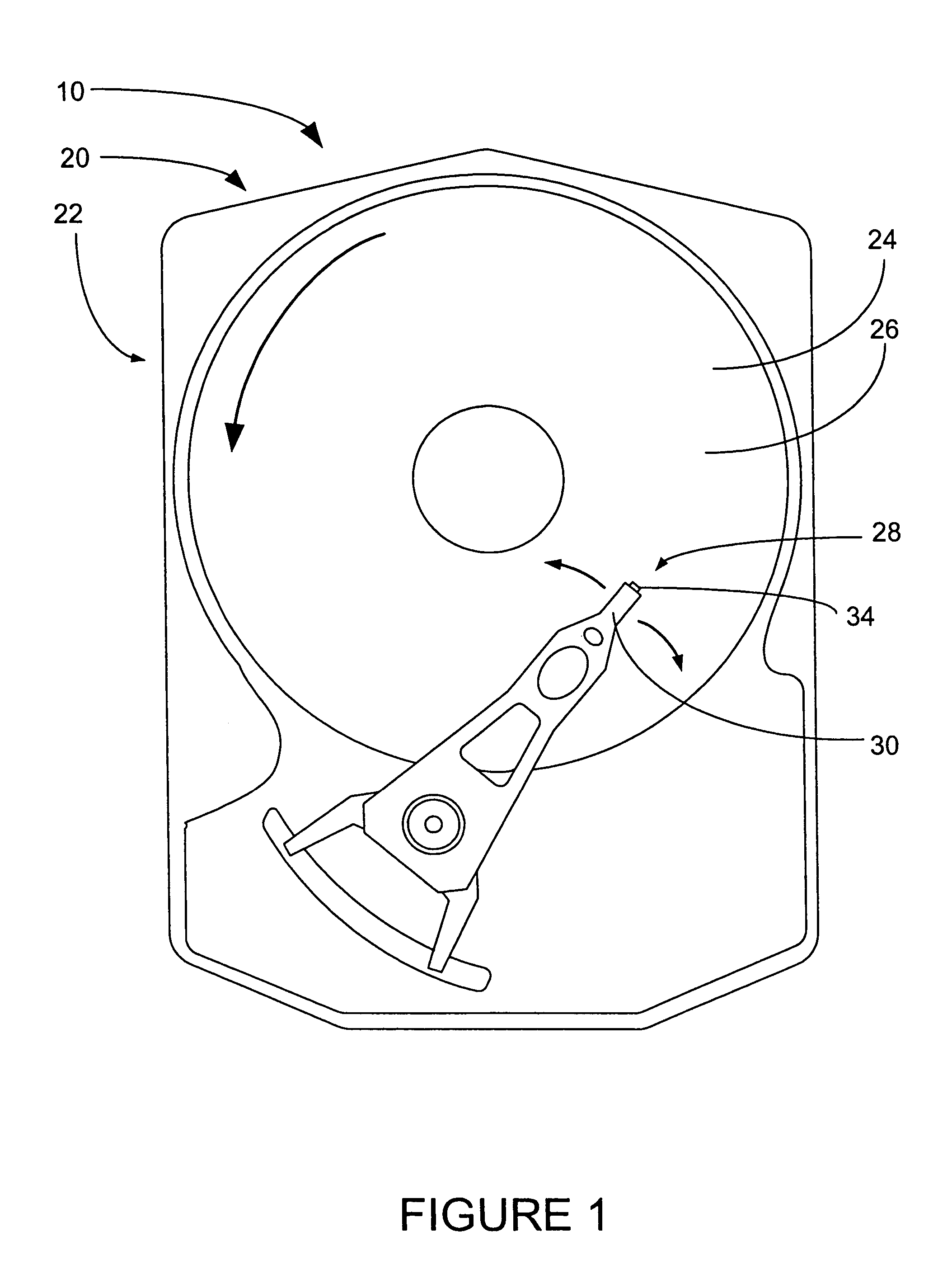
[0033]A preferred embodiment of the present invention is a disk drive having a non-corrosive slider. As illustrated in the various drawings herein, a first form of this preferred embodiment of the inventive device is depicted by the general reference character 10.

[0034]FIG. 1 shows a simplified top plan view of a magnetic storage device 20, in this case a hard disk drive 22, which generally includes a magnetic storage medium 24, specifically a hard disk 26. A data read / write device 28 includes an arm 30, which supports a slider 34.

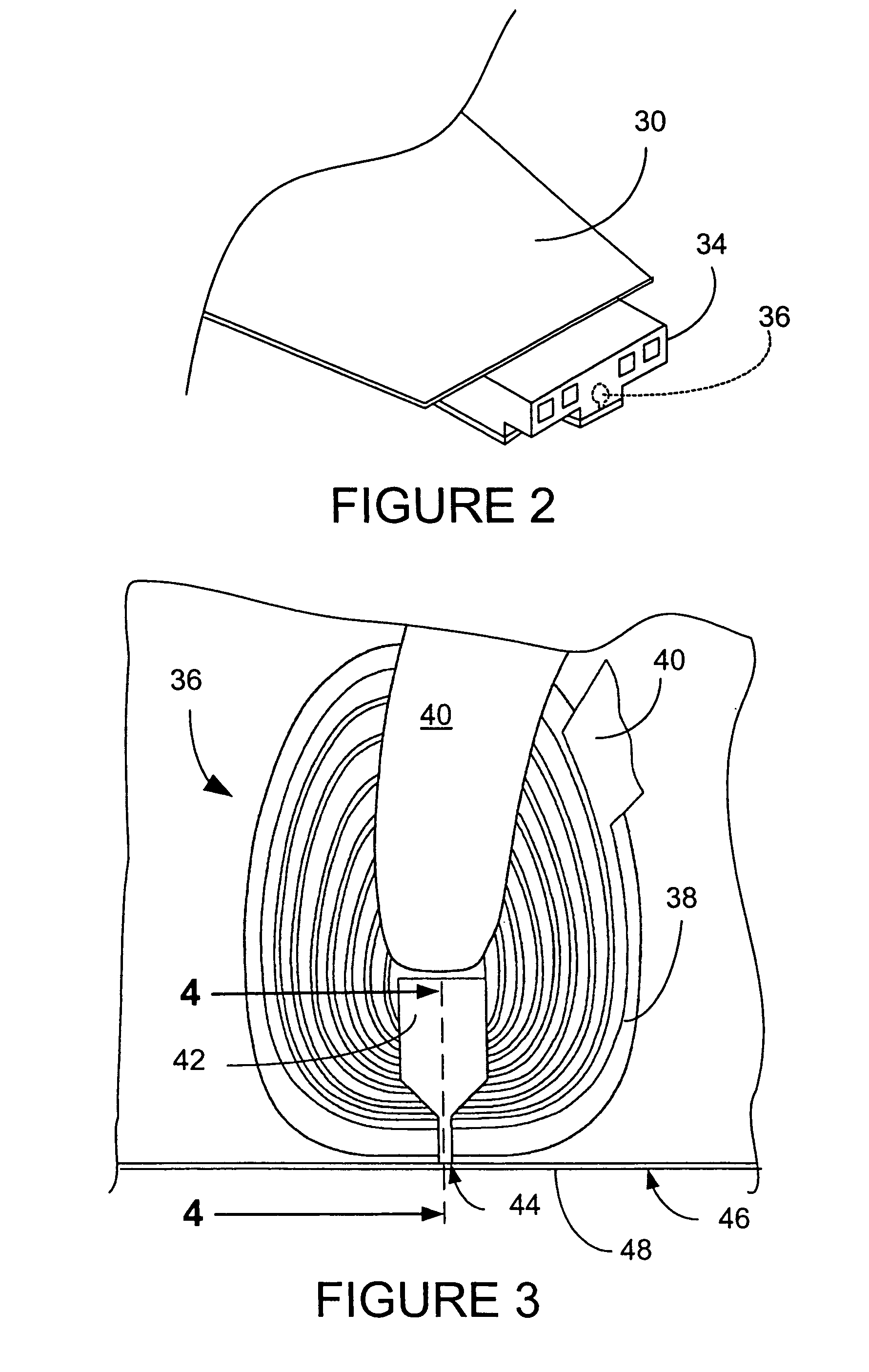
[0035]FIG. 2 illustrates a simplified isometric detail view of the slider 34 showing the arm 30 and a magneto-resistive head 36 which has been embedded in the slider 34.

[0036]FIG. 3 shows a top plan view of the components of the magneto-resistive head 36, including a coil 38, leads 40, a top pole piece 42 having a pole tip 44. The surface facing the media disk is supported by a layer of air which is established due to the rotation of the disk under the sli...


PUM

PropertyMeasurementUnit
Antiferromagnetismaaaaaaaaaa
Areaaaaaaaaaaa

Abstract

A method of fabrication of a slider includes forming a first ferromagnetic layer, a second ferromagnetic layer, and an antiferromagnetic layer and applying a layer of protective material to proximal ends of those layers that are proximal to the disk surface. The method further includes recessing a proximal end of a non-magnetic metal layer formed on the first ferromagnetic layer from the disk surface to form at least one recessed area. The method also includes filling the recessed area with protective material to a depth such that when the layer of protective material is worn from the ends of the first ferromagnetic layer, the second ferromagnetic layer, and the antiferromagnetic layer by burnishing of the ends by the disk surface, protective material still remains in the recessed area of the non-magnetic metal layer.

Description

[0001]This patent application is a divisional patent application of and claims priority to U.S. patent application Ser. No. 09 / 747,202 filed on Dec. 21, 2000, now issued as U.S. Pat. No. 6,721,142, the contents of which are incorporated herein by reference.TECHNICAL FIELD[0002]The present invention relates generally to recording heads used in magnetic media storage devices, and more particularly to magneto-resistive disk drive heads.BACKGROUND ART[0003]Disk drives containing Giant Magneto-Resistive (GMR) heads typically are supported above a disk drive surface by a thin film of air. The Air Bearing Surface (ABS) of the head flies above the disk surface by the air layer produced by the rotation of the disk surface beneath the head. Since the sensitivity of the head sensor depends on the gap spacing of the ABS above the disk surface, it is desirable that this gap distance be as small as possible, in order to produce the maximum sensitivity in the sensor. The typical gap spacing is cur...

Claims


Application Information

Patent Timeline
IPC IPC(8): G11B5/193G11B5/40G11B5/31G11B5/39
CPCB82Y10/00B82Y25/00G11B5/3106G11B5/3903G11B5/3116G11B5/313Y10T29/49044G11B2005/3996Y10T29/49032Y10T29/49043Y10T29/49041Y10T29/47
Inventor MEYER, DALLAS W.LIN, TIEN-CHIHSTACY, MICHAEL A.
Owner WESTERN DIGITAL TECH INC
Why Eureka
Try Eureka