
Blast resistant window

Inactive Publication Date: 2007-02-13
AIR FORCE THE US SEC THE
View PDF25 Cites 14 Cited by
  • Summary
  • Abstract
  • Description
  • Claims
  • Application Information

AI Technical Summary

Benefits of technology

[0010]It is another object of the invention to provide a blast resistant window having a protection against leaking of biological or chemical substances through the window structure.
[0011]It is another object of the invention to

Problems solved by technology

A terrorist attack with explosives, chemical, and / or biological weapons is a potential threat to both the civilian population and military forces.
One of the weakest points on a structure is the window and transparent glass area.
Many casualties may result from shattered and flying glass.
Additional casualties may result from subsequent chemical and or biological weapon exposure caused by the air leaks created by the broken window.
However, presently, separate solutions are insufficient to combat the combined threat.
None of these structures have demonstrated a capability for resisting blast loads on the order of 100 psi reflected pressure.
Currently available, commercial off-the-shelf, blast-resistant windows typically fail at blast pressures well below 10 psi, and usually can withstand blast pressures of only about 4 psi.

Method used


Image

  • Blast resistant window
  • Blast resistant window
  • Blast resistant window

Examples


first embodiment

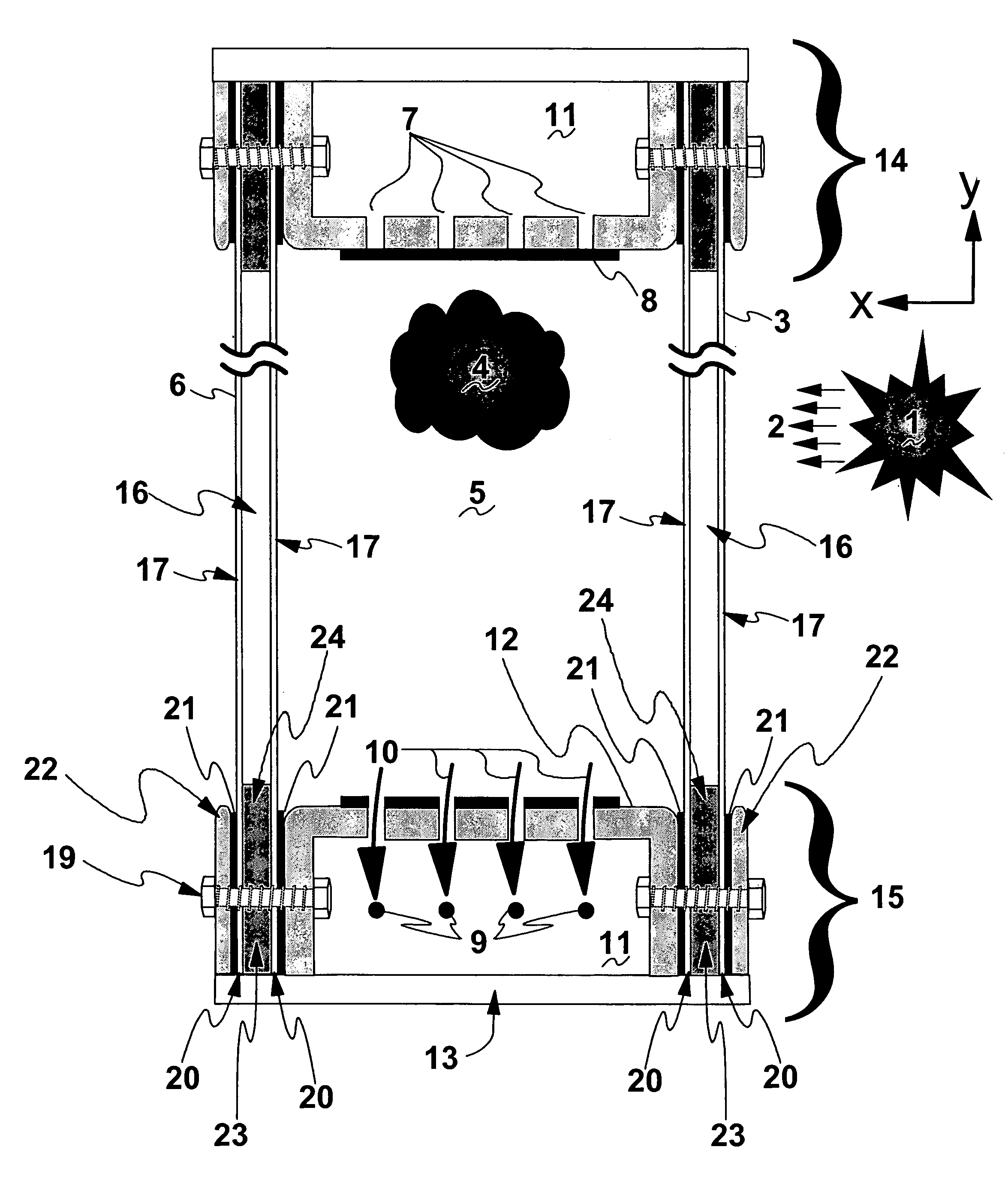
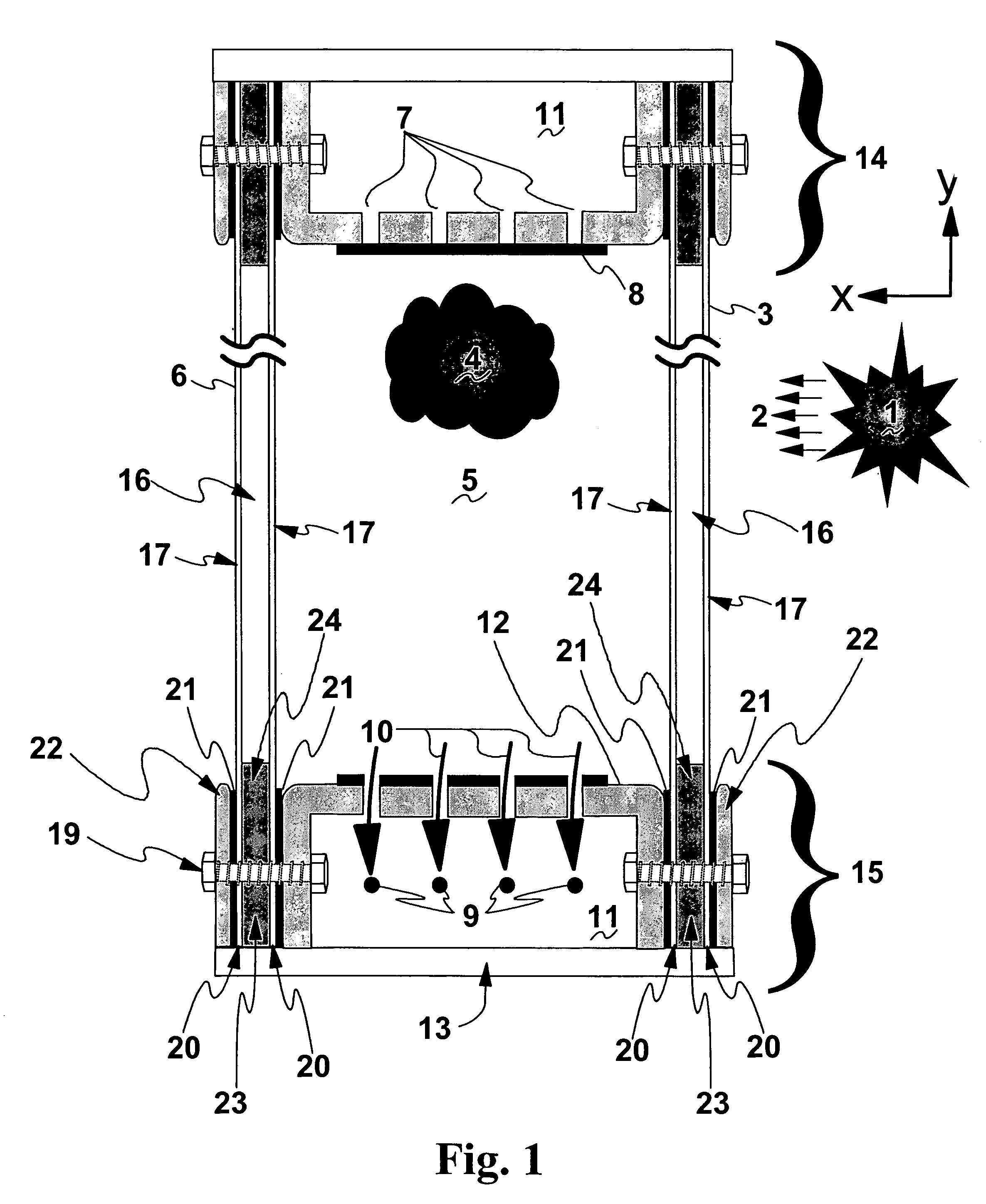
[0039]Referring now to the drawings, FIG. 1 shows a vertical side sectional view of a double pane window structure of the invention, referred to herein as the “Flex” window. As suggested in FIG. 1, an explosion 1 causes a near-planar blast wave 2 to impact the front window panel 3. The front window panel 3 deflects inwardly (i.e., in the x direction), in turn causing a build-up in pressure 4 inside the damping chamber 5. The buildup in pressure 4 within damping chamber 5 will then tend to deform the back panel 6 (also in the x direction). The damping chamber 5 has one or more vent holes 7 that vary in number, size, and spacing in relation to the surface area, aspect ratio, and distance between the front and back panels (that is, they vary in relation to the geometry of the panels and the volume of air within the damping chamber 5). Vent holes 7 are sealed by tape 8 of substantially any type as would occur to the skilled artisan practicing the invention and of varying thickness / stren...

second embodiment

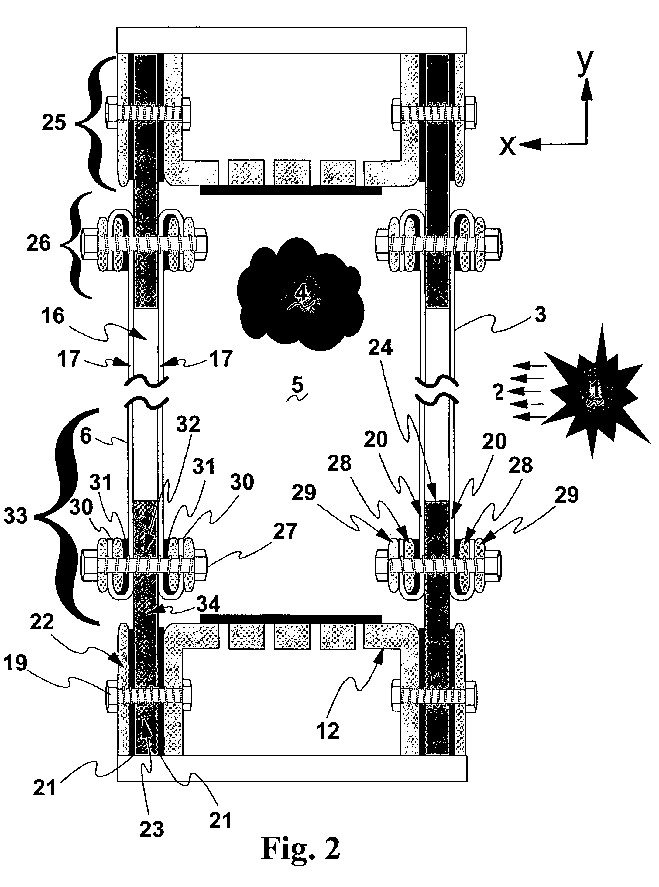
[0040]FIG. 2 shows a vertical side sectional view of a double pane window structure of the invention, including an alternate film-anchoring system and referred to herein as the Super-Flex window. In manner similar to the function of the FIG. 1 structure, an explosion 1 sends a near-planar blast wave 2 toward front panel 3, which flexes inwardly in the x direction, causing pressure 4 to build up in the damping chamber 5. Panels 3 and 6 comprise glass panes 16 covered on both sides with polymer films 17 having marginal film tails 20. Each glass pane abuts against butyl rubber mounting frame 23. The window structure of FIG. 2 has a two part anchoring system including both a metal frame assembly 25 and a film tail anchoring assembly 26. Examining first the metal frame assembly 25, it is different from the FIG. 1 structure only in that there are no film tails 20 within the frame 12,22. As before, the bolt 19 compresses the outer frame 22 toward the inner frame 12, anchoring mounting fram...


PUM


Abstract

A blast resistant window structure capable of withstanding typical car bomb blast pressures of 100 psi or more and of resisting leakage of chemical or biological agents is described, the window structure including a frame hermetically enclosing two glass panels in confronting relationship defining an air gap therebetween, each glass panel having a thin layer of polymer film on each surface thereof, and a pressure relief valve in the frame for releasing air pressure from within the gap in response to blast pressure imposed on an outer surface of one of the panels.

Description

CROSS-REFERENCE TO RELATED APPLICATION[0001]This application claims priority of the filing date of Provisional Application Ser. No. 60 / 424,280 filed Nov. 6, 2002, the entire contents of which are incorporated by reference herein.RIGHTS OF THE GOVERNMENT[0002]The invention described herein may be manufactured and used by or for the Government of the United States for all governmental purposes without the payment of any royalty.BACKGROUND OF THE INVENTION[0003]The present invention relates generally to window structures for buildings, vehicles or other applications, and more particularly to a blast resistant window capable of withstanding blast pressures from accidental explosions, or bomb blasts from a car bomb or terrorist attack.[0004]A terrorist attack with explosives, chemical, and / or biological weapons is a potential threat to both the civilian population and military forces. One of the weakest points on a structure is the window and transparent glass area. Many casualties may r...

Claims


Application Information

Patent Timeline
IPC IPC(8): E04C2/34A47F9/02
CPCE06B5/125E06B5/12
Inventor VICKERS, RICHARD N.ROCHEFORT, MICHAEL A.ANDERSON, MARK
Owner AIR FORCE THE US SEC THE
Learn More