Method and apparatus for electrorefining impure hydrogen

a technology of impure hydrogen and electrorefining, which is applied in the direction of electrolysis components, water/sewage treatment by electrochemical methods, separation processes, etc., can solve the problems of reducing the lifetime and operating efficiency of fuel cells, reducing the range of vehicle applications, and virtually unlimited hydrogen supply

Inactive Publication Date: 2007-02-13
TACTICAL FUEL CELLS
View PDF10 Cites 7 Cited by
  • Summary
  • Abstract
  • Description
  • Claims
  • Application Information

AI Technical Summary

Benefits of technology

[0017]The electrolytic cathode comprises a substrate with a material catalytic towards the decomposition of water to form hydrogen and hydroxyl ions deposited thereon. The catalytic material comprises a host matrix including one or more elements selected from Ni, Mo, Co, or combinations thereof. The catalytic material may further comprise one or more modifier elements selected from Ti, Mo, Ta, Zn, Cr, Nb, Mn, Fe, V, Cu Sr, Si, La, Ce, O, Co, Al, C, Ru, Misch metal, Raney Nickel, or combinations thereof.

Problems solved by technology

While the world's oil reserves are rapidly being depleted, the supply of hydrogen remains virtually unlimited.
Contaminated hydrogen streams containing such impurities can greatly reduce the lifetime and operating efficiency of a fuel cell.
Contaminated hydrogen streams may also dramatically affect the operating efficiency of hydrogen combustion engines resulting in shorter ranges for vehicle applications.
Impure hydrogen can be adverse to such reactions, especially in wide scale manufacturing processes, as the impurities can react to produce unwanted side products, which must be removed from the final product, or reduce the reaction efficiency, resulting in higher production costs.
The methods using fossil fuels have a built in disadvantage in that the hydrogen streams produced by such methods contain contaminates such as carbon monoxide, carbon dioxide, methane, and various hydrocarbons.
To remove carbon monoxide, methods such as selective oxidation of CO in the presence of a catalyst are presently used, however, this results in a build-up of CO2 within the hydrogen stream.
Selective adsorption of impurities in the impure hydrogen stream via Pressure Swing Adsorption to provide a pure hydrogen stream is also used, however, while this results in a product with a high purity, not all of the impurities are removed.
Other methods used to remove contaminants utilize conventional metallic membranes or hydrogen permeable membranes to purify hydrogen, but purification is not 100%, so they may also require the use of a methanation catalyst, which catalyzes the conversion of CO to methane (CH4).
While the presence of methane in the hydrogen stream may be suitable in some systems, other systems may be adversely affected by its presence.

Method used


Image

  • Method and apparatus for electrorefining impure hydrogen
  • Method and apparatus for electrorefining impure hydrogen
  • Method and apparatus for electrorefining impure hydrogen

Examples


second embodiment

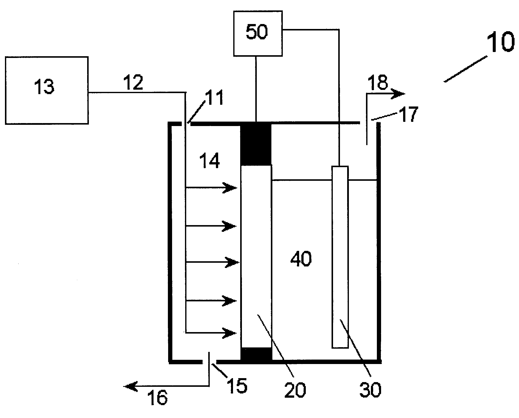
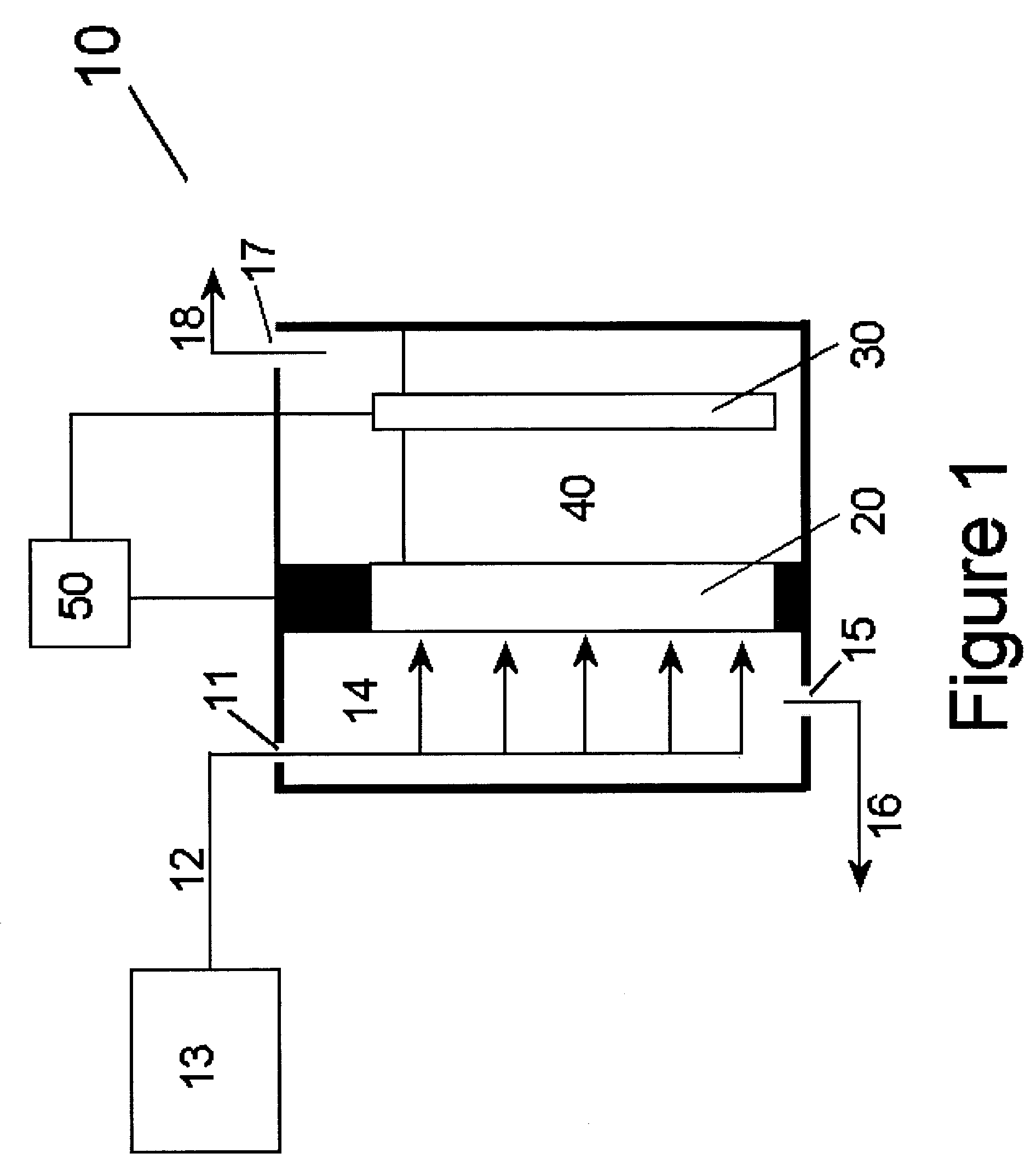
[0035]In the present invention shown in FIG. 3, the contaminant rich gas stream 16 exiting the gas receiving chamber 14 may be recycled into the impure hydrogen stream entering the purification system via a recycle stream 60 and enter the gas receiving chamber 14. This embodiment is used to recover any hydrogen exiting the gas receiving chamber with the contaminant gases. To prevent a buildup of contaminant gases within the purification system, a control system may be utilized to measure the concentration of hydrogen in the stream exiting the gas receiving chamber, whereby the gas exiting the gas receiving chamber is purged from the system through a purge stream 61 when the concentration of hydrogen falls below a predetermined level.

third embodiment

[0036]In the present invention as shown in FIG. 4, two or more purification systems in accordance with the present invention may be used to conserve a majority of all hydrogen contained in the impure hydrogen stream. In this embodiment, the contaminant rich gas exiting the gas receiving chamber 14 of the first hydrogen purification system 10 is input into a second gas receiving chamber 14A in a second hydrogen purification system 10A in accordance with the present invention. The contaminant rich stream 16 enters the second gas receiving chamber 14A and the hydrogen from the stream is absorbed into the gas diffusion anode 20A and a pure stream of hydrogen is produced at the electrolytic cathode 30A in the same manner as described above. The contaminant rich stream 16A then exits the second gas receiving chamber 14A and is vented, collected, or further processed to remove any additional hydrogen if feasible while the resulting hydrogen stream 18A is combined with the hydrogen stream 1...

fourth embodiment

[0037]In the present invention shown in FIG. 5, the contaminant rich gas stream 16 exiting the gas receiving chamber 14 may pass through a hydrogen separation system 70 which removes most of the contaminants from the contaminant rich gas stream 16 exiting the gas receiving chamber 14. The hydrogen separation 70 system may include metallic membranes, hydrogen permeable membranes, hydrogen getter materials, or any other means for separating a substantial amount of the contaminant gases from the hydrogen gas. In such case, the hydrogen rich stream 71 exiting the hydrogen separation system 70 is recycled into the impure hydrogen stream 12 entering the purification system and enters the gas receiving chamber 14 while the contaminant rich stream 72 is vented to the atmosphere or collected.


PUM

PropertyMeasurementUnit
operating temperaturesaaaaaaaaaa
weight percentaaaaaaaaaa
operating temperatureaaaaaaaaaa

Abstract

A method and system for electrochemically purifying an impure stream of hydrogen. Hydrogen is absorbed into a gas diffusion anode from the impure hydrogen stream and oxidized to form hydrogen ions and electrons which are released into an alkaline solution. An electrolytic cathode also positioned in the alkaline solution decomposes water to form hydrogen and hydroxyl ions which combine with the hydrogen ions to maintain equilibrium of the system.

Description

FIELD OF THE INVENTION[0001]The present invention relates generally to a method and system for purifying an impure stream of hydrogen. More particularly, the present invention relates to a system for electrochemically purifying an impure stream of hydrogen.BACKGROUND[0002]Considerable attention has been given to the use of hydrogen as a fuel or fuel supplement. While the world's oil reserves are rapidly being depleted, the supply of hydrogen remains virtually unlimited. Hydrogen, although presently more expensive than petroleum, is a relatively low cost fuel. Hydrogen has the highest density of energy per unit weight of any chemical fuel and is essentially non-polluting since the main by-product of burning hydrogen is water. Hydrogen is typically used as a chemical reducer in industrial processes or as a fuel to power fuel cells or hydrogen combustion engines, which in turn provide power to vehicles or other applications. To operate efficiently, such applications require a highly pu...

Claims


Application Information

Patent Timeline
Patent Type & Authority Patents(United States)
IPC IPC(8): C25B1/02C02F1/46C02F1/461C25B1/00C25B1/04
CPCC02F1/4604C02F1/46104C25B1/003C25B1/04C02F2001/46166Y02E60/368C02F2201/46165C02F2103/08Y02E60/36C25B1/55
Inventor VENKATESAN, SRINIVASANWANG, HONGDHAR, SUBHASH K.OVSHINSKY, STANFORD R.
Owner TACTICAL FUEL CELLS
Why Eureka
Try Eureka