
Ion trap device and its adjusting method

a technology of ion trapping and adjusting method, which is applied in the direction of particle separator tube details, instruments, separation processes, etc., can solve the problems of not always optimal mass resolution of all the devices, and achieve the effect of maximizing the shift of resonant frequency, maximizing phase difference, and improving mass analysis quality

Active Publication Date: 2007-02-13
SHIMADZU CORP
View PDF5 Cites 8 Cited by
  • Summary
  • Abstract
  • Description
  • Claims
  • Application Information

AI Technical Summary

Benefits of technology

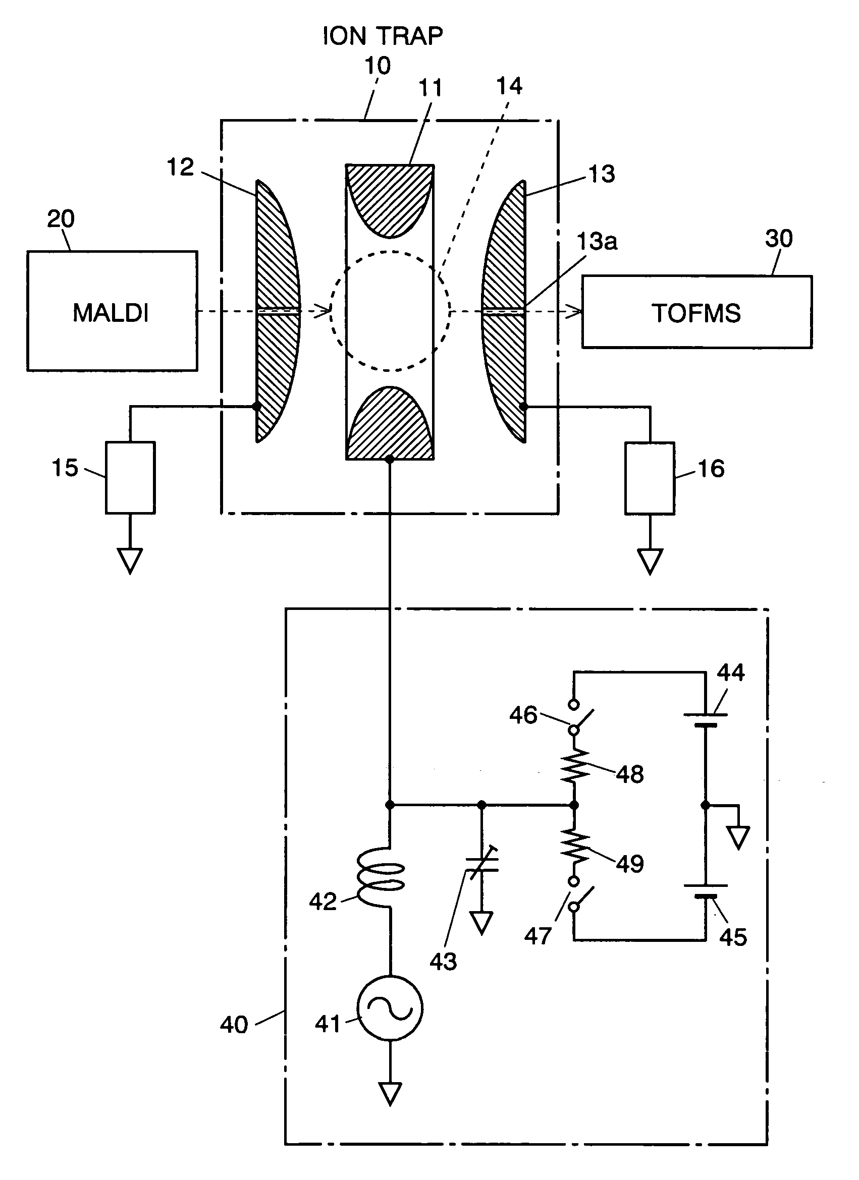
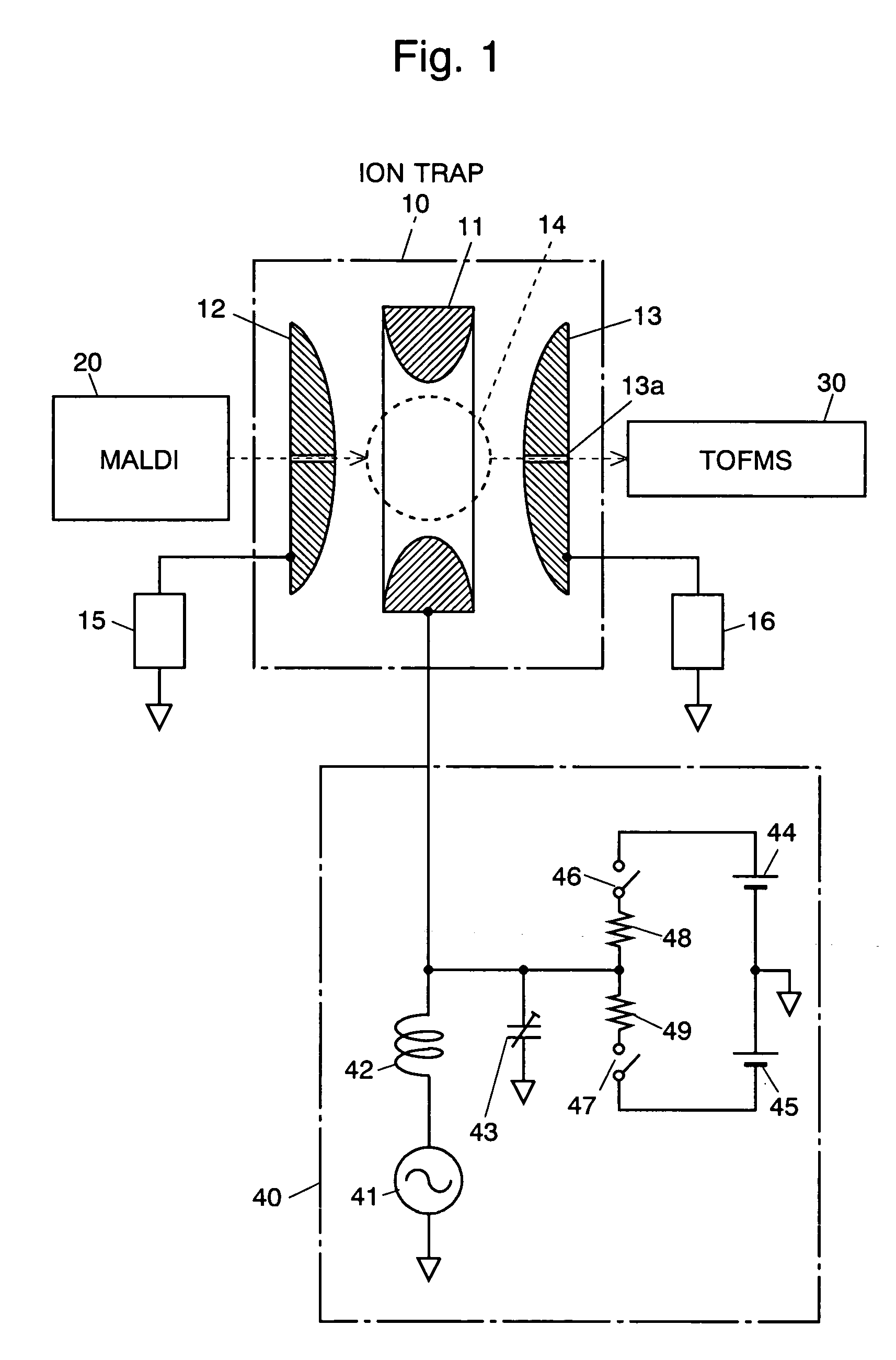
[0011]In the ion trap device disclosed in Reference 1, deviation of the phase difference between the RF driving voltage of the RF driving circuit and the RF high voltage is decreased, and the qualities of the mass analyses relating the phase, such as shift of the mass peaks, is prevented from deteriorating. But the amount of the shift of the resonant frequency may differ from device to device, and Reference 1 does not clearly describe a concrete method of determining the amount of the shift. As indicated in Reference 1, deviation of the phase difference becomes less as the amount of the shift of the resonant frequency is larger, and the qualities of the mass analyses are improved more. As described at paragraph 0024 of Reference 1, specifically, the resonant frequency of the resonant circuit is shifted so that, when the target amplitude of the RF high voltage is set at its highest value, the RF driving voltage of the RF driving circuit reaches its highest possible value. This maximizes the shift of the resonant frequency of the resonant circuit from the frequency of the RF driving voltage, and also maximizes the phase difference between the RF driving voltage and the RF high voltage, which minimizes the influence of the change of the resonant frequency when the RF high voltage is changed to the phase difference.
[0013]Thus an object of the present invention is to provide an ion trap device in which the phase difference between the RF driving voltage and the RF high voltage is always adjusted at a constant value, and many devices can be set at the optimal condition.

Problems solved by technology

But the amount of the shift of the resonant frequency may differ from device to device, and Reference 1 does not clearly describe a concrete method of determining the amount of the shift.
When the same values of the timing of the operation are used for the devices, their influence on the phase difference between the RF driving voltage and the RF high voltage differs among devices, and the qualities, such as the mass resolution, of all the devices are not always optimal.

Method used


Image

  • Ion trap device and its adjusting method
  • Ion trap device and its adjusting method
  • Ion trap device and its adjusting method

Examples


Embodiment Construction

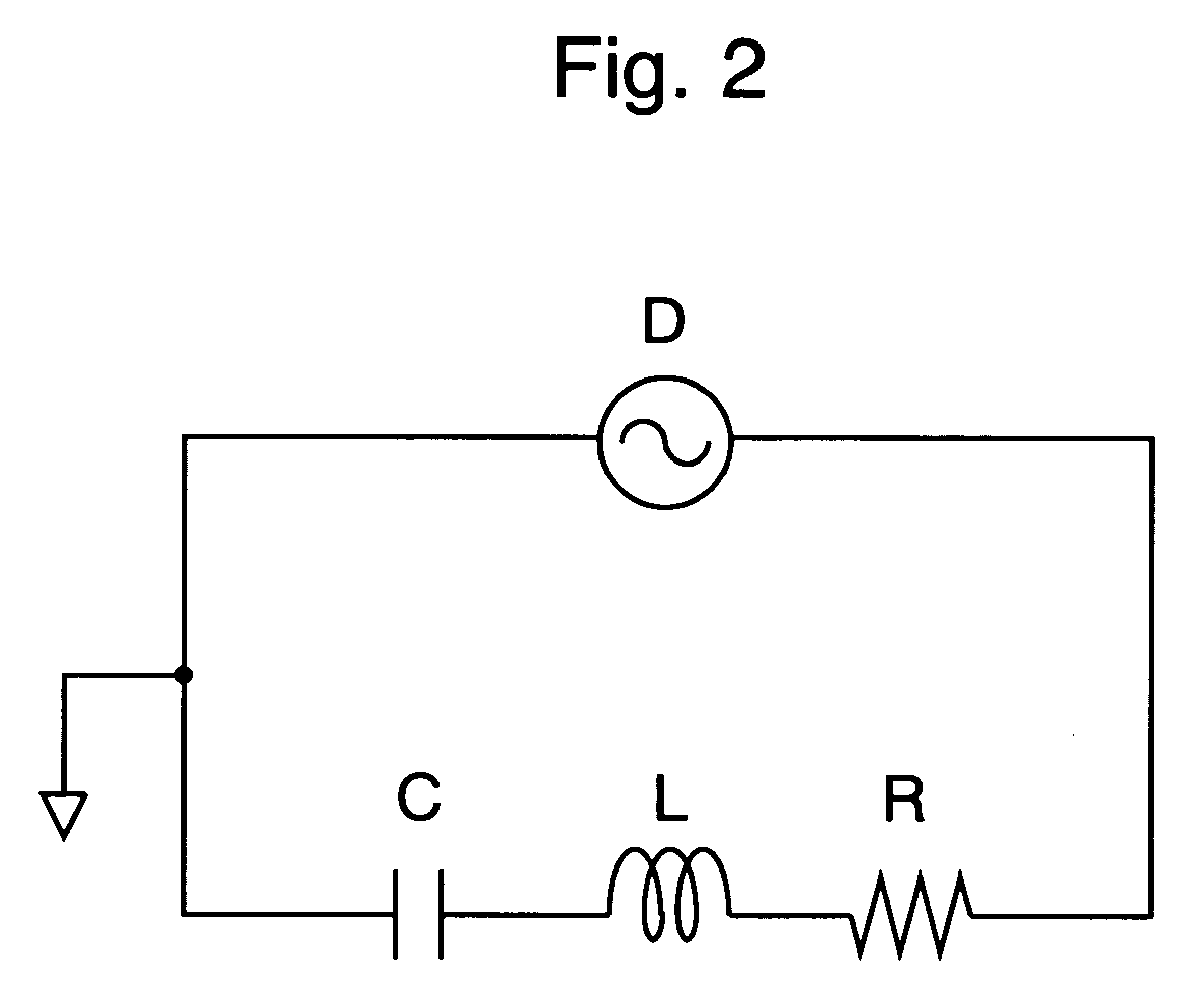
[0032]The principle of operation of the present invention is described referring to the simplified LCR series resonant circuit diagram shown in FIG. 2. The total capacitance is represented by C, the inductance of the coil is represented by L, and the equivalent resistance of the resonant circuit is represented by R. The angular frequency of the RF driving voltage generated by the RF driving circuit D is represented by ω0, and the resonant angular frequency of the resonant circuit is represented by ω, where an angular frequency ω is a frequency multiplied by 2π. The impedance Z of the resonant circuit is given by

Z=R+jX,

where

X=ωL−1 / (ωC).

[0033]In the first step (step 1), the resonant angular frequency ω of the resonant circuit is made equal to the angular frequency ω0 of the RF driving voltage by adjusting the inductance L or the capacitance C. Then the resonance condition is satisfied, and X becomes zero (X=0). In this case, as derived from the above equation, the impedance Z of the r...


PUM

PropertyMeasurementUnit
resonant frequencyaaaaaaaaaa
driving voltageaaaaaaaaaa
voltageaaaaaaaaaa

Abstract

In an ion trap device including: a plurality of electrodes enclosing an ion trapping space for trapping ions; an RF driving circuit for generating an RF driving voltage; a resonant circuit for amplifying the RF driving voltage and applying an RF high voltage to at least one of the plurality of electrodes; and a tuning circuit for adjusting a resonant frequency of the resonant circuit while keeping the amplitude of the RF high voltage constant, the method of adjusting the ion trap device according to the present invention includes the steps of: adjusting a resonant frequency of the resonant circuit to a frequency of the RF driving voltage; and shifting the resonant frequency of the resonant circuit so that the RF driving voltage increases by a predetermined constant ratio. According to the ion trap device and its adjusting method of the present invention, the phase difference between the RF driving voltage of the RF driving circuit and the RF high voltage, θ, is adjusted to the same value in plural devices even if the parameters of various elements constituting the resonant circuit, such as the inductance or the equivalent resistance, are slightly different from device to device. Thus the influence of the change in the resonant angular frequency Δω when the amplitude of the RF high voltage is changed to the phase difference θ, Δθ, is the same among devices, and the qualities, such as the mass resolution, of all the devices are always set at their optimal, even if the same parameter values are used to determine operation timings of the device.

Description

[0001]The present invention relates to an ion trap device which uses a three-dimensional quadrupole electric field to trap ions therein. Such an ion trap device can be used in an ion trap mass spectrometer, or in a time-of-flight mass spectrometer (TOFMS) using it as the ion source.BACKGROUND OF THE INVENTION[0002]In an ion trap device, ions are trapped in a three-dimensional quadrupole electric field generated basically by combining an RF electric field and a DC electric field. One type of ion trap device is constructed with electrodes whose inner surfaces are shaped hyperboloid-of-revolution so that a rather large ion trapping space is created in the space surrounded by the electrodes. Another type of ion trap device is constructed with cylindrical and disc electrodes (Cylindrical Ion Trap) in which an ion trapping space is created around the center of the space surrounded by the electrodes. In these constructions, the electrodes are composed of a ring electrode and two end cap el...

Claims


Application Information

Patent Timeline
Patent Type & Authority Patents(United States)
IPC IPC(8): B01D59/44H01J49/00G01N27/62H01J49/40H01J49/42
CPCH01J49/424H01J49/022
Inventor KAWATO, EIZO
Owner SHIMADZU CORP
Learn More