LED device and portable telephone, digital camera and LCD apparatus using the same

a technology of led devices and portable telephones, applied in the direction of instruments, discharge tubes, luminescent screens, etc., can solve the problems of unsatisfactory color reproduction characteristics of red, in particular, and difficulty in achieving bright white light with satisfactory color reproduction characteristics, and achieve good color reproduction characteristics and bright white light

Active Publication Date: 2007-02-13
SHARP KK
View PDF12 Cites 42 Cited by
  • Summary
  • Abstract
  • Description
  • Claims
  • Application Information

AI Technical Summary

Benefits of technology

[0009]The present invention was made in order to solve the above described problem, and its object is t

Problems solved by technology

The white LED device described above, however, attains quasi-white emission by the combination of blue light and fluorescent light of yellow as a complementary color of blue, and therefore, color reproduction characteristic of red, in particula

Method used


Image

  • LED device and portable telephone, digital camera and LCD apparatus using the same
  • LED device and portable telephone, digital camera and LCD apparatus using the same
  • LED device and portable telephone, digital camera and LCD apparatus using the same

Examples


example 1

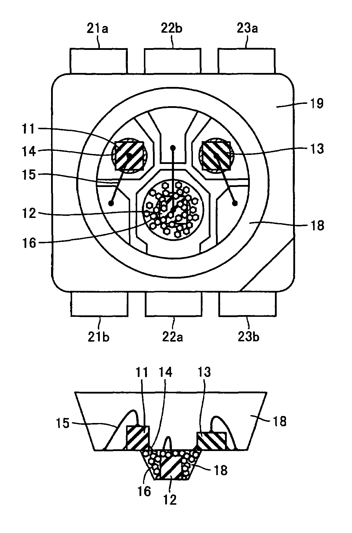
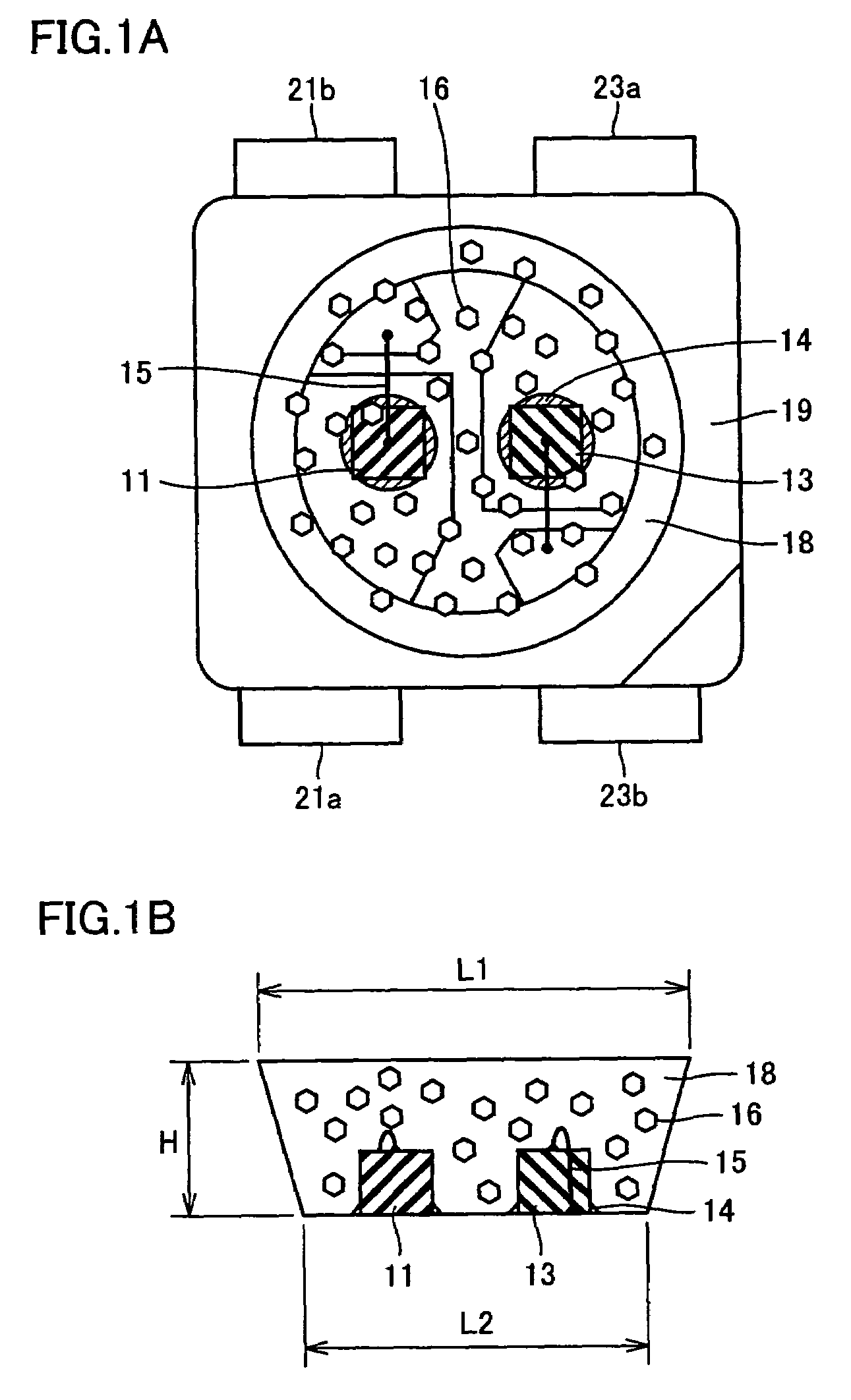
[0059]Referring to FIGS. 1A and 1B, InGaN on an SiC substrate having peak emission wavelength of 460 nm with electrodes arranged in the P / N vertically opposite arrangement was used as blue light emitting element 11, AlGaInP having peak emission wavelength of 624 nm with electrodes arranged in the P / N vertically opposite arrangement was used as red light emitting element 13, and SrGa2S4:Eu having average grain diameter of 8 μm was used as green fluorescent substance 16. Terminal electrodes 21a, 21b, 23a and 23b were of Cu alloy and coated with Au plating for better wire-bonding. As conductive adhesive 14, Ag paste was used, and Au wire was used for wire-bonding 15. As light transmitting resin 18, a thermosetting epoxy resin (specific gravity: 1.2) was used.

[0060]The LED device shown in FIGS. 1A and 1B was manufactured through the following steps. First, at prescribed positions of terminal electrodes 21a and 23a in a reflective case 19, n-electrodes of blue light emitting element 11 a...

example 2

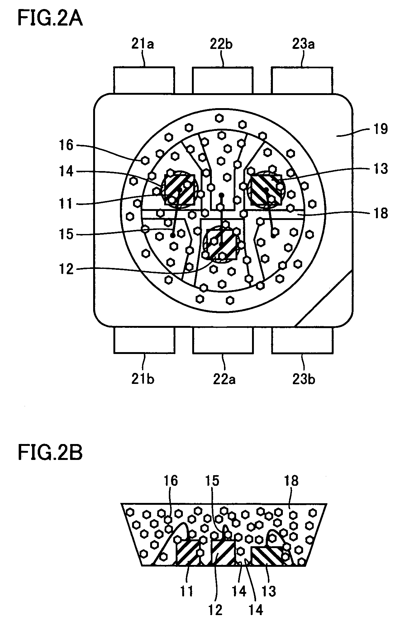
[0064]Referring to FIGS. 2A and 2B, GaN having peak emission wavelength of 405 nm with electrodes arranged in the P / N vertically opposite arrangement was used as ultraviolet / violet light emitting element 12. Red light emitting element 13, green fluorescent substance 16, terminal electrodes 21a, 21b, 23a and 23b, conductive adhesive 14, bonding wire 15 and light transmitting resin 18 were the same as those used in Example 1. An LED device was fabricated through similar steps as in Example 1.

[0065]In the LED device, when only the red light emitting element 13 was driven with 35 mA, red light having the luminous intensity in axial direction of 1.1 cd was obtained, when only the blue light emitting element 11 was driven with 35 mA, blue-green light having the luminous intensity in axial direction of 1.1 cd was obtained because of the green fluorescent light from green fluorescent substance 16, when only the ultraviolet / violet light emitting element 12 was driven with 35 mA, green light ...

example 3

[0066]An LED device was fabricated in the similar manner as in Example 2, except that SrAl2O4:Eu was used in place of SrGa2S4:Eu as green fluorescent substance 16 and that in 1 g of light transmitting resin, 0.1 g of green fluorescent substance was kneaded.

[0067]In the LED device, when only the red light emitting element 13 was driven with 35 mA, red light having the luminous intensity in axial direction of 1.1 cd was obtained, when only one blue light emitting element was driven with 35 mA, blue light having the luminous intensity in axial direction of 0.5 cd was obtained with the green fluorescent substance being hardly excited, when only the ultraviolet / violet light emitting element 12 was driven with 35 mA, green light having the luminous intensity in axial direction of 1.4 cd was obtained through green fluorescent substance 16, and when all light emitting elements were driven with 35 mA, white light having the luminous intensity in axial direction of 3.0 cd and CIE chromaticity...


PUM


Abstract

An LED device at least including a blue light emitting element having peak emission wavelength of 420 nm to 480 nm, a green fluorescent substance having peak wavelength of fluorescent spectrum in the range of 500 nm to 580 nm with the emission of the blue light emitting element, and a red light emitting element having peak emission wavelength of 600 nm to 670 nm is provided. The device may further include an ultraviolet/violet light emitting element for exciting green fluorescent substance. As a result, an LED device capable of attaining bright white light with good color reproduction characteristic is provided.

Description

[0001]This nonprovisional application is based on Japanese Patent Application No. 2003-115987 filed with the Japan Patent Office on Apr. 21, 2003, the entire contents of which are hereby incorporated by reference.BACKGROUND OF THE INVENTION[0002]1. Field of the Invention[0003]The present invention relates to an LED (Light Emitting Diode) device used as an auxiliary light source of a CCD (charge coupled device) or a CMOS (Complementary Metal Oxide Semiconductor) camera or as a backlight source of an LCD (Liquid Crystal Display). More specifically, the present invention relates to an LED device having superior color reproduction characteristic and emitting bright white light, including a combination of a light emitting element and a fluorescent substance excited by the light emitting element.[0004]2. Description of the Background Art[0005]As a conventional white light emitting device using an LED, a white LED device has been known (see, for example, Japanese Patent Laying-Open No. 200...

Claims


Application Information

Patent Timeline
IPC IPC(8): H01L27/15H01L29/26G02F1/13357C09K11/08C09K11/54C09K11/56C09K11/58C09K11/59C09K11/62C09K11/64C09K11/66C09K11/77C09K11/80H01J1/62H01L25/075H01L33/44H01L33/50H01L33/56H04N5/225H04N101/00
CPCC09K11/0883C09K11/584C09K11/595C09K11/62C09K11/662C09K11/7729C09K11/7734C09K11/7792H01L25/0753H04N5/2256C09K11/54H01L33/504H01L2224/48465H01L33/502Y02B20/181H01L2224/45144H01L2224/48091H01L2224/48247H01L2924/00014H01L2924/00H01L2924/181Y02B20/00H04N23/56H01L2924/00012
Inventor OMOTO, MASATOSHIMASUDA, MASATSUGUKITANO, MASAHARU
Owner SHARP KK
Why Eureka
Try Eureka