Bouncing mode operated scanning micro-mirror

a micro-mirror and bouncing mode technology, applied in the field of tilting micro-mirrors, can solve the problems of high uncertainty, difficult to provide, and difficult to meet, and achieve the effects of improving linearity, improving accuracy, and improving scanning performan

Active Publication Date: 2007-02-13
STMICROELECTRONICS INT NV +1
View PDF2 Cites 26 Cited by
  • Summary
  • Abstract
  • Description
  • Claims
  • Application Information

AI Technical Summary

Benefits of technology

[0011]The present invention discloses a tilting “bouncing mode” micro-mirror that uses either an additional stiffness element (also referred to throughout this description as “bouncer”) or a pre-curved nonlinear stiffness element to achieve a superior scanning performance. The present invention further discloses a micro-mechanical actuator used to move a member carrying a payload (e.g. a mirror) along an axis in a periodical nonlinear angular trajectory. The present invention further discloses a novel tilting micro-mirror mode of operation that permits the achievement of a piecewise linear response of a micro-mirror device operated by intrinsically nonlinear forces. In one embodiment, the “bouncing mode” of operation according to the present invention includes a contact event between the mirror and an elastic constraint, which takes place each time the mirror reaches a prescribed rotation angle. This contact event is followed by the bouncing of the mirror and by the inversion of the angular motion, hence the name “bouncing mode”. In another embodiment, the “bouncing mode” is achieved by the action of pre-curved nonlinear stiffness elements coupled at one end to an actuator and at another end to the mirror. Illustrative examples of bouncing-mode scanning micro-mirrors actuated electro-statically by both parallel-plate electrodes and planar or vertical comb drives are presented in detail. It is shown that in all embodiments, the response frequency can be tuned through the control of the actuation voltage. This feature allows to compensate for uncertainties in the parameters of micro-fabricated devices and to synchronize the response frequency with a precision sufficient for video applications. The resonant-mode operation and the application of actuation forces during the contact event, when the mirror is close to the electrode (in the bouncer plus parallel plate actuation example), enable operation at extremely low power and voltages and provide a compact and low cost actuator. Additional improvements in linearity may be achieved through the application of a correction voltage during the mirror motion between bouncing events.
[0014]Other important advantages of the devices and methods disclosed herein include low sensitivity of the frequency and shape of the output signal to the system parameters, and good controllability of frequency. These advantages arise from the fact that the frequency of the mirror is defined by the deformation of the barrier, which for its part depends on the level of the energy supplied during each bouncing event. Viscous losses during the free motion, as well as uncertainties in the system parameters, can be easily compensated by controlling this energy supplement through the actuation voltage. Note that the uncertainty in the resonance frequency of the mirror can be critical, as mentioned in H. Wada et al. above, who reported a discrepancy of 25–30% between calculated and measured values. This ability to tune the natural frequency using the actuation voltage permits long-term stabilization of the response frequency and precise synchronization of the mirror motion with a video input.

Problems solved by technology

For example, in optical communication applications, the requirements of long term positioning accuracy combined with high optical quality and low thermal sensitivity are the most challenging.
While linear motions are highly desirable in all micro-mirrors, it is difficult to provide it.
The difficulty is mainly the consequence of the intrinsic nonlinearity and high level of uncertainty of operational forces developed by MEMS actuators.
However, the price paid is usually a high power consumption resulting in high heat generation, intricacy of the design and relatively complicated fabrication processes.
In addition, the scaling laws of magnetic actuators are less favorable that those of electrostatic actuators.
However, the central difficulty of electrostatic actuation is the intrinsic nonlinearity of electrostatic forces.
Moreover, the nonlinearity of electrostatic forces combined with the linearity of elastic restoring mechanical forces lead also to pull-in instability, which limits the operational range of the device.
The necessity to provide a triangular signal which is required for video applications leads to very high actuation voltages or, in the case of magnetic actuation, very large currents.
This difficulty is not related to the linearity of the motion and it is a result of high angular accelerations during the inversion of the velocity.
The problems with tall such solutions include high complexity, difficulty to provide resonant frequencies with high accuracy, and consequently high sensitivity to fabrication tolerances and extreme difficulty in tuning the resonant frequency.

Method used


Image

  • Bouncing mode operated scanning micro-mirror
  • Bouncing mode operated scanning micro-mirror
  • Bouncing mode operated scanning micro-mirror

Examples


Embodiment Construction

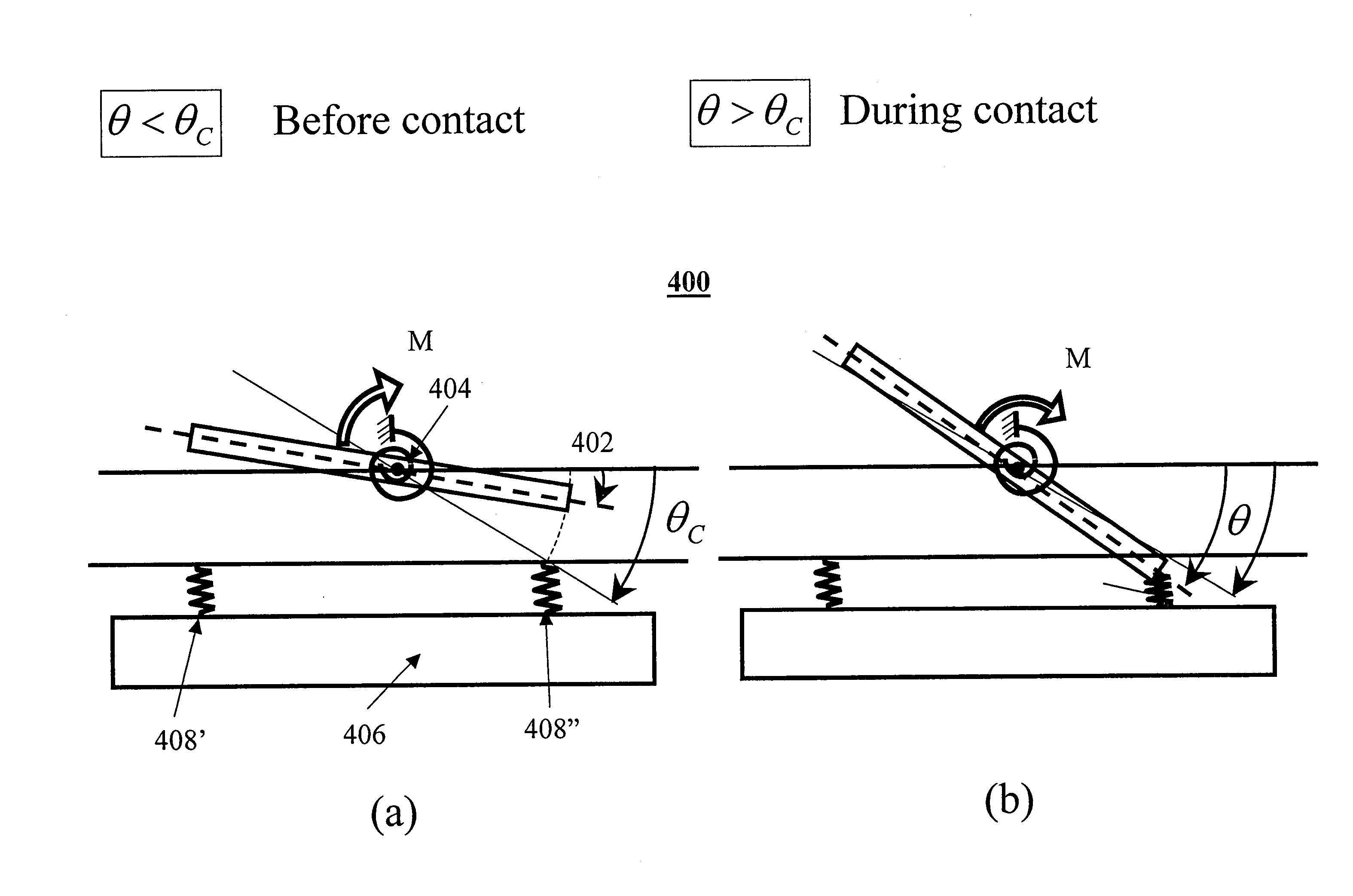
[0058]The present invention discloses a tilting bouncing mode micro-mirror that uses either an additional stiffness element (“bouncer”) or a pre-curved nonlinear stiffness element to achieve a superior scanning performance. While a bouncer such as a cantilever or beam is an element with linear stiffness, we have found inventively and advantageously that its cooperative action with other elements of the system (specifically a torsion spring) that have a different stiffness yields a combined “nonlinear stiffness element” effect. The bouncing mode uses an actuation operation mode based on a special nonlinear actuation and control principle. The “bouncing-mode” actuator that actuates the mirror is operated in the self-exciting mode and its motion is actually a limit cycle. The actuator moves the mirror in a piecewise linear trajectory. The nonlinear actuation and control principle provides a set of desirable features such as small size and weight, low power and low heat dissipation, hig...


PUM

PropertyMeasurementUnit
anglesaaaaaaaaaa
angleaaaaaaaaaa
depthaaaaaaaaaa

Abstract

A MEMS apparatus for scanning an optical beam comprises a mirror operative to perform a rotational motion to a maximum rotation angle around a mirror rotation axis formed in a double active layer silicon-on-insulator (SOI) substrate. The apparatus may include a bouncing mechanism operative to provide a bouncing event and to reverse the rotational motion. The bouncing event provides the mirror with a piecewise linear response to actuation by intrinsically nonlinear electrostatic forces. In a particular embodiment, the bouncing mechanism includes a vertical comb drive stator built in the same active layer of the double active layer SOI substrate, while actuator comb drive stators are built in a different active layer.

Description

CROSS REFERENCE TO RELATED APPLICATIONS[0001]The present invention is a continuation in part of U.S. patent application Ser. No. 10 / 902,869 filed Aug. 2, 2004, which claims priority from U.S. Provisional Patent Applications Nos. 60 / 494,353 filed Aug. 12, 2003, 60 / 550,850 filed Mar. 8, 2004, and 60 / 575,248 filed Jun. 1, 2004, the contents of which are incorporated herein by reference.FIELD OF THE INVENTION[0002]The present invention relates generally to scanning micro-mirrors implemented in Micro Electro Mechanical Systems (MEMS) or Micro Opto Electro Mechanical Systems (MOEMS), and more particularly to tilting micro-mirrors used for scanning.BACKGROUND OF THE INVENTION[0003]A tilting micro-mirror is a central element in many MEMS or MOEMS devices. When used for scanning, its elements and operation principle are shown in FIG. 1. A tilting micro-mirror (or simply “mirror”) 100 comprises a generally flat plate (e.g. made of silicon) that has a reflecting surface 104. Plate 102 is held ...

Claims


Application Information

Patent Timeline
Patent Type & Authority Patents(United States)
IPC IPC(8): G02F1/01G02B26/00G02B26/08G02F1/03G02F1/07
CPCG02B26/0841B81B3/0051G02F1/03G02F1/07G02B26/00
Inventor KRYLOV, SLAVAMEDINA, MOSHEHUBER, AVIGDORLALEZAR, RONEN
Owner STMICROELECTRONICS INT NV
Why Eureka
Try Eureka