

Implantable medical device having flat electrolytic capacitor with porous gas vent within electrolyte fill tube
a medical device and electrolytic capacitor technology, applied in the field of implantable medical devices, can solve the problems of low reliability of capacitors, battery(s) and high-voltage capacitors used to provide and accumulate the energy required for cardioversion/defibrillation shocks, and the ability to improve the reliability of capacitors
- Summary
- Abstract
- Description
- Claims
- Application Information
AI Technical Summary
Benefits of technology
Problems solved by technology
Method used
Image

Examples
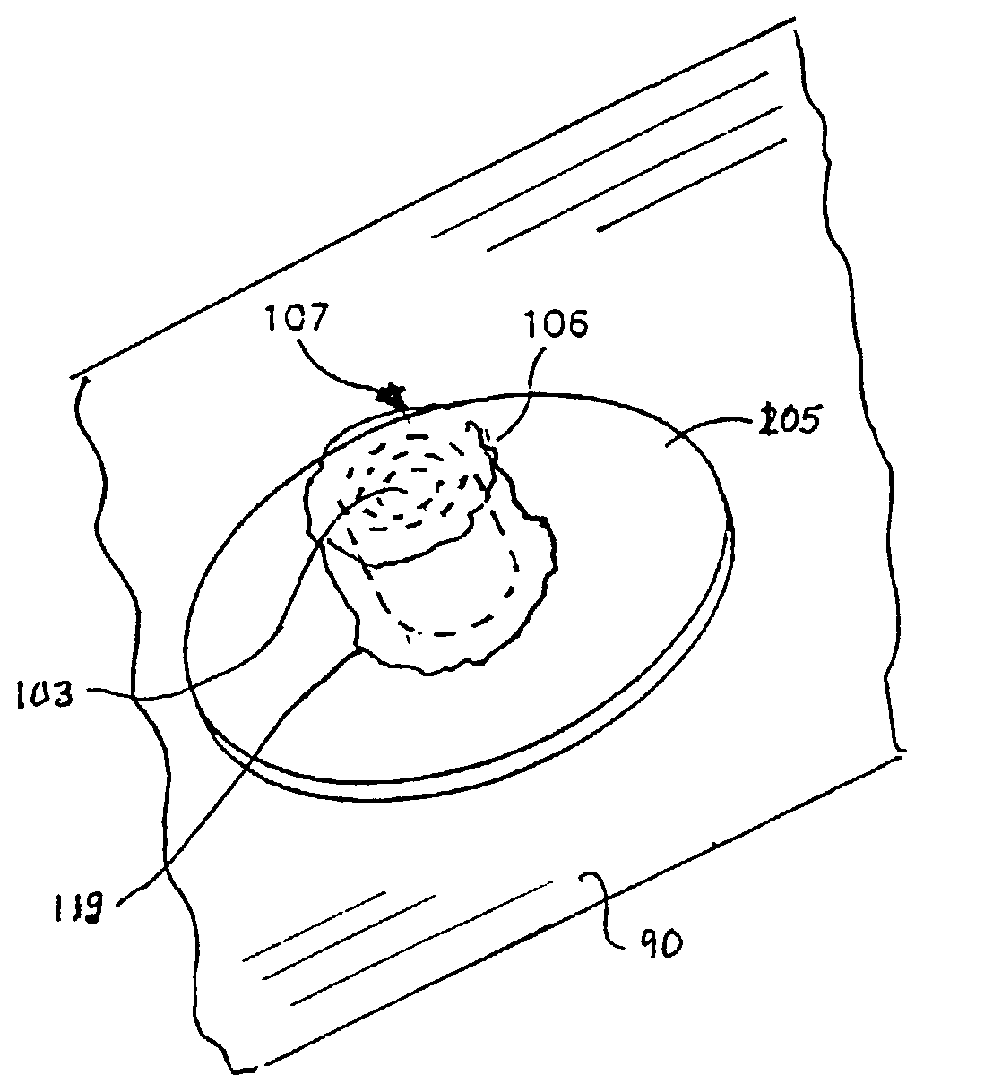
case 90
[0137]Case 90, cover 110 and capacitor 265 may additionally form a case negative capacitor (where case 90 and cover 110 are electrically connected to the cathode layers and are therefore at the same electrical potential as the cathode layers, i.e., at negative potential), or a floating case capacitor (where case 90 and cover 110 are electrically connected neither to the cathode layers nor to the anode sub-assemblies, and where case 90 and cover 110 are at substantially no electrical potential or at an electrical potential that floats with respect to the respective potentials of the cathode layers and the anode sub-assemblies). In some embodiments, case 90 or cover 110 may be formed of an electrically non-conductive material or substantially electrically non-conductive material such as a suitable plastic, polymeric or ceramic material.
[0138]Ferrules 95, 100 and 105 are most preferably welded to case 90 (or otherwise attached thereto such as by a suitable epoxy, adhesive, solder, glue...
PUM
 Abstract
Description
Claims
Application Information