High-frequency transmission line and an optical module incorporating the same line

a technology of optical modules and transmission lines, applied in waveguides, semiconductor lasers, instruments, etc., can solve the problems of increasing reflection loss, not being able to consider prior art, and causing reflection loss, and achieve the effect of increasing reflection loss

Active Publication Date: 2007-02-13
LUMENTUM JAPAN INC
View PDF8 Cites 16 Cited by
  • Summary
  • Abstract
  • Description
  • Claims
  • Application Information

AI Technical Summary

Benefits of technology

[0017]The prior art disclosed in Japanese Patent Laid-open No.2000-114801 is arranged such that a is substantially equal to (b+c×square root of 2), so that the capacitance component of the conductor adopted in the bending portion of the transmission line is larger than the counterpart of the present invention. Thus, the characteristic impedance of the conductor disclosed therein is smaller than that of the bending portion of the transmission line according to the present invention so as to increase reflection loss.

Problems solved by technology

However, the reflection loss as caused by such arrangement as disclosed in the above prior art is not disregarded, especially when it is applied to an optical module with a higher bit rate.
Further, in such a transmission line structure provided with ground lines in the same plane as a coplanar line, the same circumstances as mentioned above occurs at the bending portion of the transmission line between the respective signal wiring conductors 11a and 11b and ground wiring conductors, which results in the increase of reflection loss.
Further, the conductor adopted in the prior art as disclosed in Japanese Patent Laid-open No.2000-114801 is large in line width so as to increase the capacitance component thereof while to decrease the characteristic impedance thereof, with the result that reflection loss occurs.

Method used


Image

  • High-frequency transmission line and an optical module incorporating the same line
  • High-frequency transmission line and an optical module incorporating the same line
  • High-frequency transmission line and an optical module incorporating the same line

Examples


first embodiment

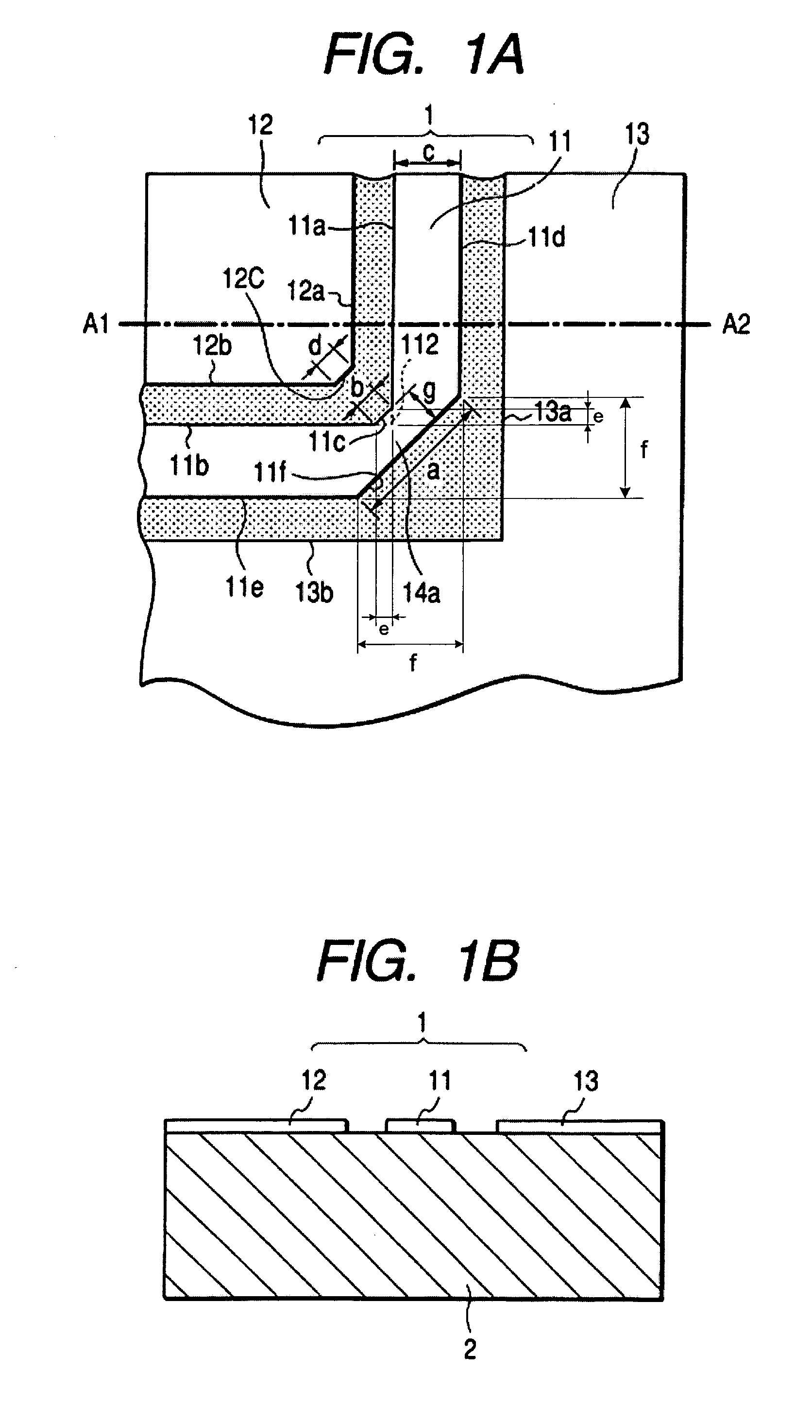
[0038]FIG. 1A is a plan view of a high-frequency transmission line according to the present invention, while FIG. 1B is a sectional view of the high-frequency transmission line taken along A1–A2 of FIG. 1A. As shown therein, a high-frequency transmission line 1 has a coplanar line configuration and comprises a signal wiring conductor 11 formed on a substrate 2 and ground wiring conductors 12 and 13 disposed at the respective sides of the signal wiring conductor 11. The substrate 2 is made of a dielectric material or alumina (Al2O3) and a gold thin film is adopted for the respective wiring conductors. The high-frequency transmission line is designed according to the dimensions prescribed for the width of the transmission direction of the signal wiring conductor 11 or the vertical direction thereof with regard to the transmission line and the interval between the respective ground wiring conductors such that the characteristic impedance of the signal wiring conductor amounts to 50Ω in...

second embodiment

[0055]Then, the present invention is described with reference to FIG. 3.

[0056]FIG. 3 is a plan view of the high-frequency transmission line according to the second embodiment, and FIG. 4 is a plan view thereof according to the third embodiment thereof. The same structural elements shown in FIG. 1 are indicated with the same references, and the explanation thereof is omitted for redundancy.

[0057]In the embodiments shown in FIGS. 3 and 4, the high-frequency transmission line 1 is a coplanar strip line wherein either the ground wiring conductors 12 or 13 is disposed on one side of the signal wiring conductor 11 in the same plane. The signal wiring conductor 11 and the ground wiring conductor 12 are formed on the substrate 2 in the same way as shown in FIG. 1. In the case of the coplanar strip line, the line configuration depends on whether the ground wiring conductor lies in the outer side of the bending portion 14a or in the inner side thereof. FIG. 3 shows the ground wiring conductor...

fourth embodiment

[0060]Then, the fourth embodiment is described with reference to FIG. 5.

[0061]FIG. 5 is a plan view of the high-frequency transmission line according to the fourth embodiment of the present invention.

[0062]The high-frequency transmission line 27 of this embodiment is provided with two bending portions 14a and 14b. The configuration of the transmission line is a coplanar line in the same as shown in FIG. 1 comprising the signal wiring conductor 11 and the ground wiring conductors 12 and 13 disposed at the respective sides of the conductor 11, which conductors are disposed in the same plane. The bending portion 14a is formed in the same way as shown in FIG. 1. The bending portion 14b is point-symmetrically positioned to the bending portion 14a. An inner ground conductor side 12c is provided in the ground wiring conductor 12, which side intersects with the inner ground wiring side 12b. An inner signal conductor side 11g is provided in the signal wiring conductor 11, which side intersec...


PUM

PropertyMeasurementUnit
angleaaaaaaaaaa
impedanceaaaaaaaaaa
frequencyaaaaaaaaaa

Abstract

A transmission line with a bending portion is provided, which line comprises any one of a coplanar line, another coplanar waveguide line formed on the dielectric substrate under which a ground layer is provided and a coplanar strip line. A chamfered portion is provided on the outer angular portion of the bending portion of the signal wiring conductor and a triangular conductor is disposed to an inner angular portion thereof. Given that length of the chamfered portion is defined as a, and length of the wiring edge side of the triangular conductor is defined as b and width of the signal wiring conductor is defined as c, it is arranged such that a is greater than b+c×square root of 2. Thereby, a transmission line or an optical module of smaller reflection loss at the bending portion thereof and of improved high-frequency characteristics is provided.

Description

FIELD OF THE INVENTION[0001]The present invention relates to a high-frequency transmission line and an optical module incorporating the same line, especially, pertaining to such transmission line as being capable of converting a signal transmission direction and being good at high-frequency characteristics and an optical module incorporating the same line.DESCRIPTION OF THE RELATED ART[0002]In an optical communication field, the data tend to be received and transmitted by a higher and higher bit rate year by year in accordance with the development of advanced information system. As to a laser module to transmit an optical signal by an optical modulator too, in order to transfer an optical signal of a higher bit rate from a transmitter to a receiver without fail, it is essential to improve the high-frequency characteristics of the transmission line that transmits an electrical signal to the optical modulator.[0003]FIG. 8 shows an upper surface view of the inside of the prior optical ...

Claims


Application Information

Patent Timeline
Patent Type & Authority Patents(United States)
IPC IPC(8): H04B10/04G02F1/03H04B10/00H01S5/022H01P1/02H01P3/02H01P3/08H01S5/026
CPCH01P1/02
Inventor MATSUSHIMA, NAOKIKAWAMOTO, KAZUMIKUWANO, HIDEYUKINIWA, YOSHIAKIKATO, TETSUYA
Owner LUMENTUM JAPAN INC
Why Eureka
Try Eureka