Lubrication system for an engine

a lubrication system and engine technology, applied in the direction of machines/engines, mechanical equipment, auxiliaries, etc., can solve the problems of deterioration of motorcycle appearance, improper driver position, and difficulty in collecting lubricant, so as to reduce engine height and reliably collect lubricant

Active Publication Date: 2007-02-20
YAMAHA MOTOR CO LTD
View PDF2 Cites 18 Cited by
  • Summary
  • Abstract
  • Description
  • Claims
  • Application Information

AI Technical Summary

Benefits of technology

[0008]The advantage of the present invention made in view of the situation described above is to provide a lubrication system for an engine capable of reducing the engine height by elevating the crankcase bottom, as well as of reliably collecting a lubricant accumulated at the bottom of the crankcase.
[0009]According to an embodiment of the present invention, a lubrication system for an engine includes an oil tank, a crankshaft, a crankcase for housing the crankshaft, an oil sump formed at the bottom of the crankcase and collecting a lubricant for circulated moving parts to be lubricated and an oil pump for returning the lubricant collected in the oil sump to the oil tank. The oil sump and an oil suction port are provided respectively on one side and the other side of a normal plane including an axis of the crankshaft.
[0010]The oil pump is provided only on the one side, and the oil suction port provided on the other side is connected to the oil pump through a suction passage.
[0011]The present invention relates to a lubrication system for an engine, wherein the suction passage is disposed in a region offset from a crank arm in an axial direction of the crankshaft.
[0012]The present invention also relates to a lubrication system for an engine, wherein the suction passage is formed with a separate pipe member from the crankcase, and disposed outside of the crankcase.
[0013]According to the present invention, on one pump shaft of the oil pump are mounted first and second rotors for sucking a lubricant accumulated in the oil sump from the suction port, and a third rotor for delivering the lubricant in the oil tank to the moving parts to be lubricated.

Problems solved by technology

In addition, the single cylinder or two-cylinder engine with a larger cylinder internal volume inevitably has a larger crank throw radius and a longer piston stroke, compared to the multi-cylinder engine with the same displacement.
This results in the fuel tank being provided in a higher position, causing the motorcycle to have a deteriorated appearance and an improper driver's position.
Therefore, the lubricant accumulated at the bottom of the crankcase is dispersed forward and rearward of the crankshaft, making it difficult to collect the lubricant.

Method used


Image

  • Lubrication system for an engine
  • Lubrication system for an engine
  • Lubrication system for an engine

Examples


Embodiment Construction

[0047]The embodiments of the present invention will be hereinafter described in reference to the appended drawings.

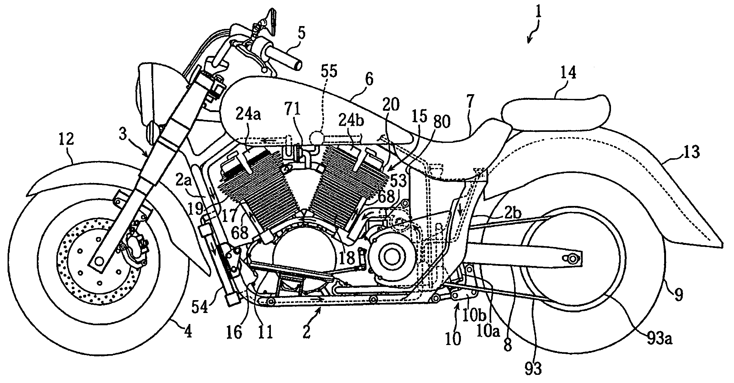
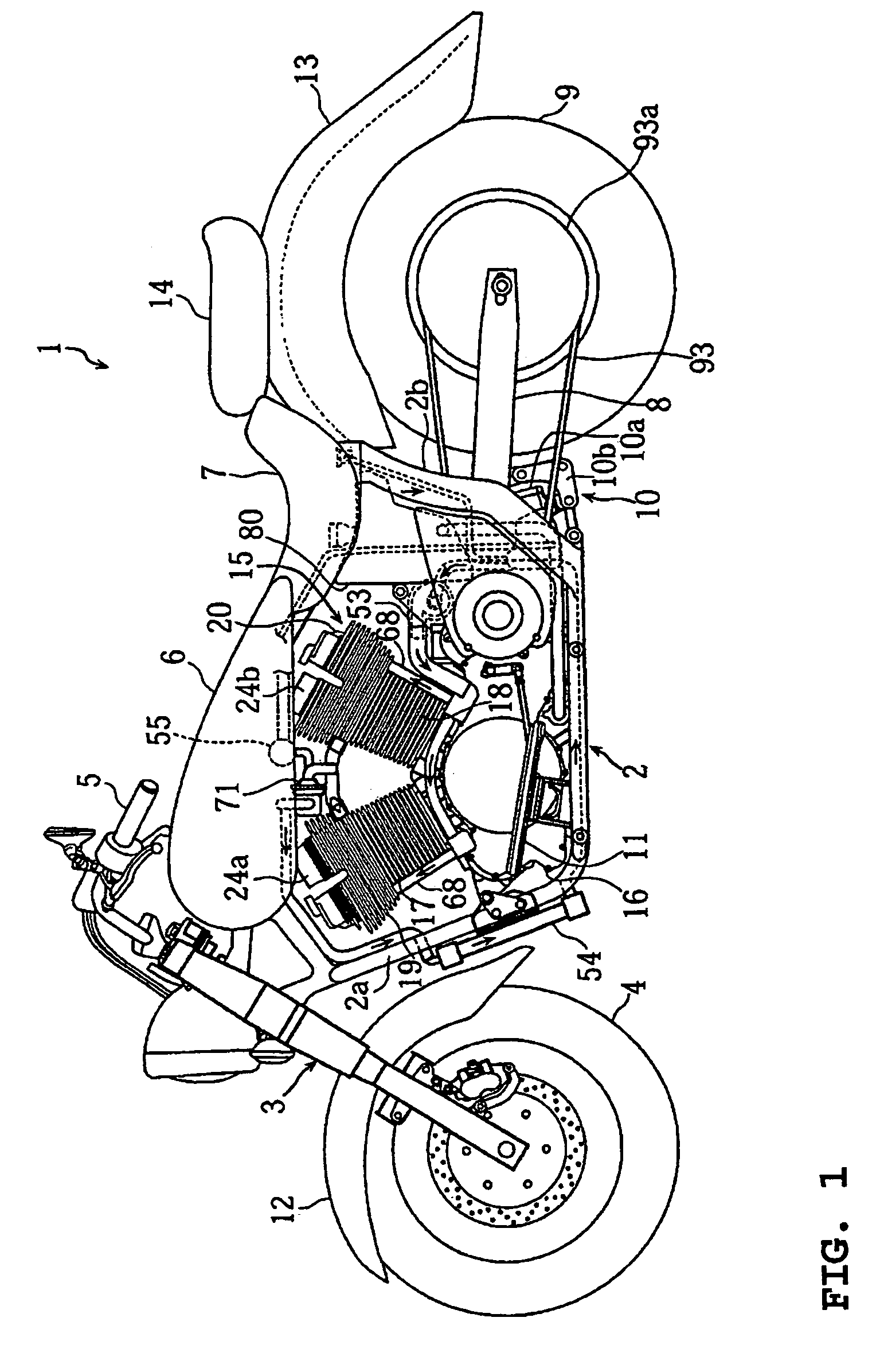
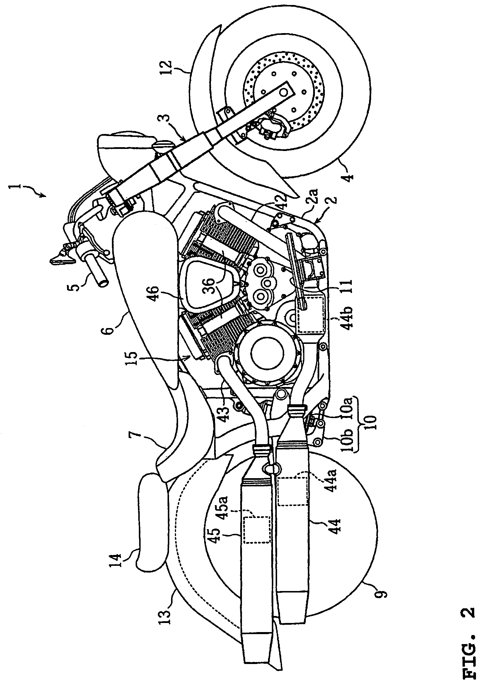
[0048]FIG. 1–FIG. 20 are views illustrating a lubrication system for an engine according to an embodiment of the present invention. FIG. 1 and FIG. 2 are left side and right side views, respectively, of a motorcycle carrying an engine of this embodiment. FIG. 3 and FIG. 4 are sectional right side views of the engine. FIG. 5 is a sectional rear view of the engine. FIG. 6 is a sectional plan view of the engine. FIG. 7 is a sectional plan view of a power transmission section of the engine. FIG. 8 is an overall view of a partial water cooling system of the engine. FIG. 9 is a sectional side view of a water pump section of the partial water cooling system. FIG. 10 is a sectional view taken along the line X—X of FIG. 9. FIG. 11 is a bottom view of a cylinder head. FIG. 12 is a sectional view taken along the line XII—XII of FIG. 11. FIG. 13 is a block diagram of the partial wa...


PUM


Abstract

A lubrication system for an engine includes an oil tank, a crankshaft, a crankcase for housing the crankshaft. An oil sump formed at a bottom of the crankcase collecting lubricant for circulated moving parts to be lubricated, and an oil pump for returning the lubricant collected in the oil sump to the oil tank are also provided. The oil sump and an oil suction port are provided, respectively, on one side and the another side of a normal plane including an axis of the crankshaft.

Description

BACKGROUND OF THE INVENTION[0001]1. Field of the Invention[0002]This invention relates to a dry sump lubrication system which delivers a lubricant in an oil tank to moving parts to be lubricated in an engine by an oil pump, and returns the lubricant collected in an oil sump to the oil tank.[0003]2. Description of Related Art[0004]A single cylinder or two-cylinder engine with a large displacement generally causes a larger reciprocating mass of a piston and toque variations during a combustion stroke, compared to a multi-cylinder engine with the same displacement. Therefore, the single and two-cylinder engines tend to need a thick, large-diameter crank arm in order to increase the moment of inertia.[0005]In addition, the single cylinder or two-cylinder engine with a larger cylinder internal volume inevitably has a larger crank throw radius and a longer piston stroke, compared to the multi-cylinder engine with the same displacement. Therefore, the single and two-cylinder engines tend t...

Claims


Application Information

Patent Timeline
Patent Type & Authority Patents(United States)
IPC IPC(8): F01M1/00F02B61/02F01M1/02F01M1/06F01M1/12F01M11/00F01M11/02F01P5/10F02F7/00
CPCF01M1/12F01M1/02F01M11/02F02B61/02F01M2001/126F01P5/10F01M2001/123
Inventor TAKEUCHI, YOSHIHIKO
Owner YAMAHA MOTOR CO LTD
Why Eureka
Try Eureka