Coaxial DC block

a dc block and coaxial cable technology, applied in the direction of coaxial cables/analogue cables, cables with twisted pairs/quads, electrical equipment, etc., can solve the problems of low frequency noise, low frequency noise introduction, configuration problems, etc., to reduce interference, increase capacitance, and reduce the effect of external interferen

Active Publication Date: 2007-02-20
ADVANTEST CORP
View PDF8 Cites 15 Cited by
  • Summary
  • Abstract
  • Description
  • Claims
  • Application Information

AI Technical Summary

Benefits of technology

[0008]The present invention is a novel coax DC block that dramatically increases the capacitance across the outer coax connection in such a way that the ground path impedance is very low as a function of frequency and outside interference is minimized.
[0009]By improving the coax ground connection, low frequency noise performance is improved while not degrading high frequency performance. Improvement will depend on system conditions and ambient noise conditions.

Problems solved by technology

However, some applications, for example large systems that utilize both high and low frequency signals, may be susceptible to low frequency noise (e.g., approximately 1 kHz and below) caused by ground loops.
Thus, the coax connection between the RF rack and semiconductor test interface may complete a ground loop between the RF rack and digital tester which can introduce low frequency noise.
However, such a configuration is problematic.
This results in noise being introduced into the system.
This solution is problematic due to the coaxial configuration of the coaxial cable transmission line.
Although the insertion of a capacitor between the two inner conductors of the two lengths of coaxial cables is straightforward, the insertion of a capacitance between the two outer conductors of the two lengths of coaxial cables is problematic.
The insertion of a capacitor between the two outer conductors of the two lengths of coaxial cables generally degrades the shielding characteristics of the coaxial cable and adversely affects the integrity of signals propagated through the coaxial cable.
Although some DC blocks have been developed which capacitively break the outer coax connection, to date, these DC blocks do not have low enough impedance when the desired signal propagation frequency range includes lower frequencies (but greater than the very low frequencies seen on ground loops).
Greater impedance at low frequencies can introduce low frequency noise on the propagated signals.
In the prior art DC blocks, the outer connection is limited in capacitance due to its construction.

Method used


Image

  • Coaxial DC block
  • Coaxial DC block
  • Coaxial DC block

Examples


Embodiment Construction

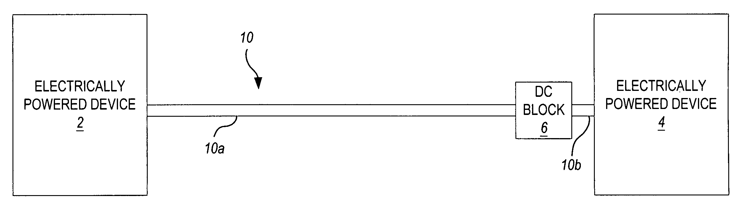
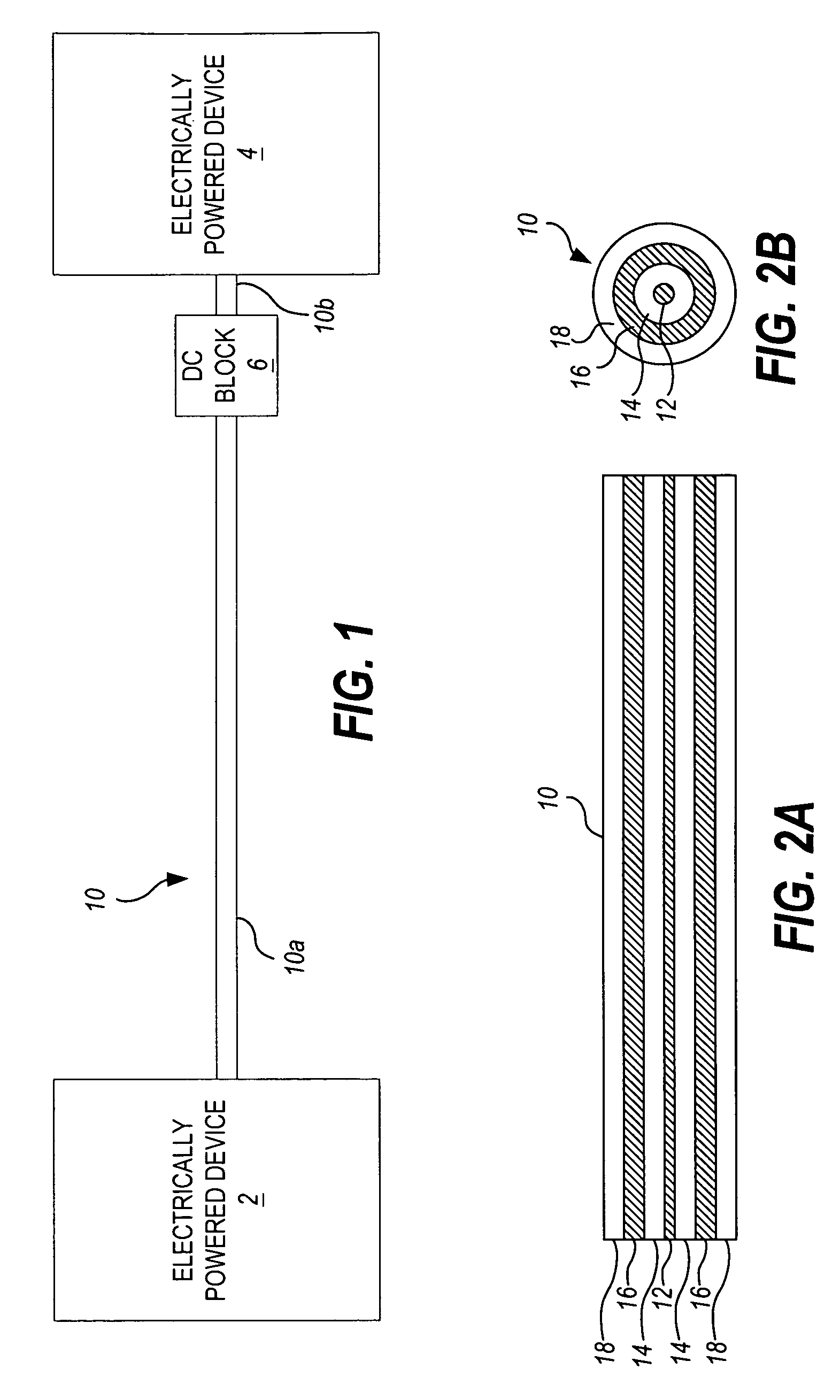
[0042]Turning now to the drawings, FIG. 1 illustrates a coaxial cable connection between two devices. A coax DC block is inserted in series along the coaxial cable connection in order to eliminate DC and low frequency voltage or current components while allowing high frequency signals.

[0043]FIG. 2A is a cut-away view of a length of coaxial cable 10, and FIG. 2B is a view of a cross-section of the coaxial cable 10 of FIG. 2A. As shown therein, the coaxial cable 10 is formed of concentric inner and outer conductors 12 and 16, a dielectric 14 sandwiched between the inner conductor 12 and outer conductor 16, and an insulator 18 concentrically surrounding the outer conductor 16.

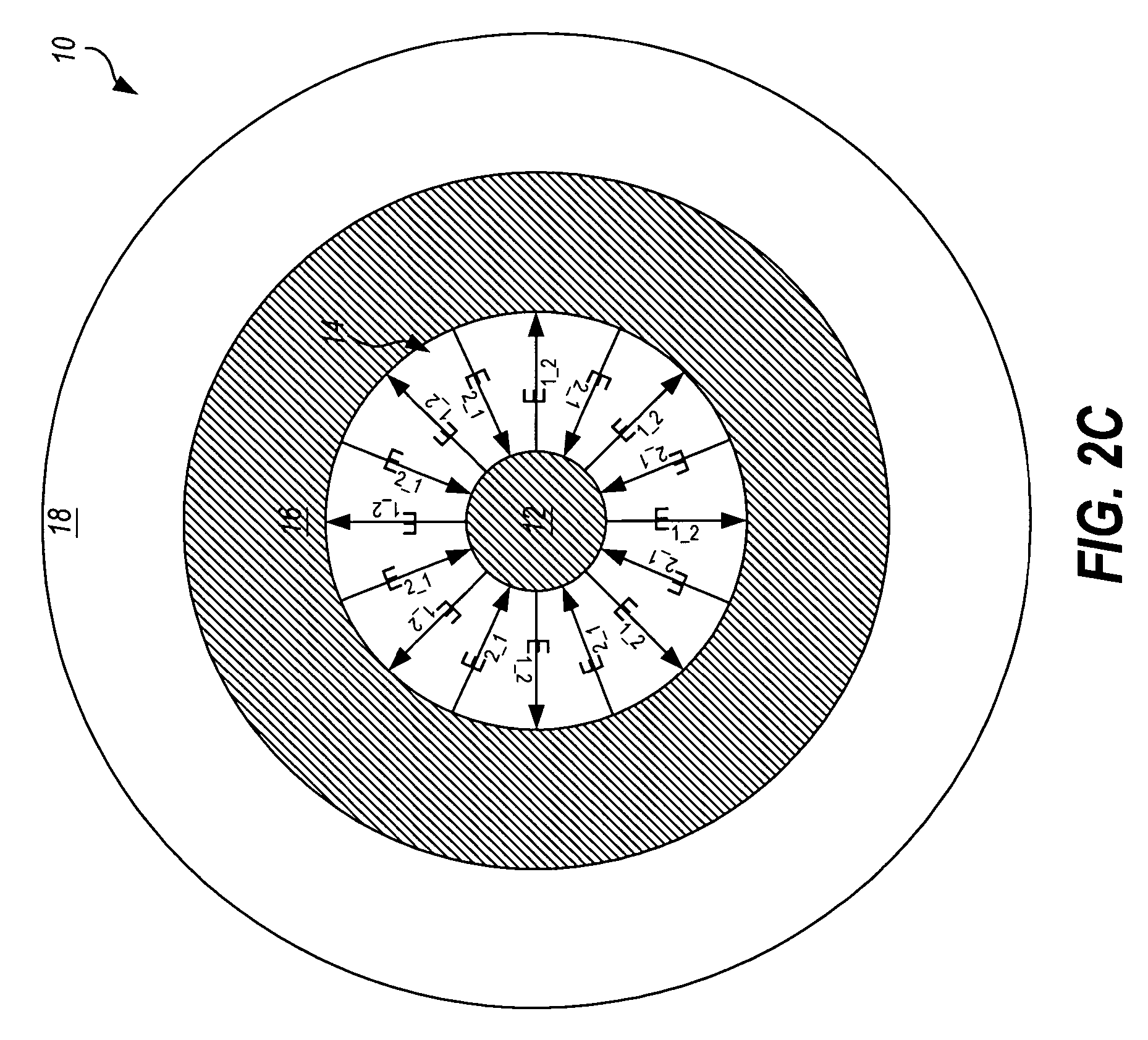
[0044]FIG. 2C is an electric field diagram illustrating the electric fields generated by a signal propagating along the coaxial cable 10. According to standard electromagnetic field theory, the electric field Ei generated by current flowing in one direction (e.g., into the page) on the inner conductor 12 radiates ...


PUM

PropertyMeasurementUnit
frequencyaaaaaaaaaa
capacitanceaaaaaaaaaa
frequencyaaaaaaaaaa

Abstract

A novel coaxial DC block with circumferential capacitive shielding is presented. The coaxial DC block includes an inner DC block electrically couplable to a first inner conductor of a first length of coaxial cable and electrically couplable to a second inner conductor of a second length of coaxial cable. The inner DC block provides a capacitance which capacitively couples the first inner conductor to the second inner conductor and blocks a first frequency range of interest. The inner DC block is electrically sealed and shielded by a capacitive sleeve that is concentrically arranged to form a Faraday cage around the inner DC block. The capacitive sleeve is electrically couplable to a first outer conductor of the first length of coaxial cable and electrically couplable to a second outer conductor of the second length of coaxial cable. The capacitive sleeve forms a circumferential capacitance that electrically circumferentially couples the first outer conductor to the second outer conductor and blocks a second frequency range of interest.

Description

BACKGROUND OF THE INVENTION[0001]As known in the art, a coaxial cable is formed of two concentric conductors separated by a dielectric. This unique construction results in the restriction of the electromagnetic field to the region between the inner and outer conductors, which results in near perfect shielding between fields inside and outside the cable.[0002]Coaxial cables are generally used to propagate high-frequency signals from one electrical device to another. Generally, both electrical devices can be at the same ground potential. However, some applications, for example large systems that utilize both high and low frequency signals, may be susceptible to low frequency noise (e.g., approximately 1 kHz and below) caused by ground loops. In this case, it is desirable to break up potential ground loops. One way to do this is to break the ground connection in the coax line. For example, in industrial RF semiconductor testers, which require testing in both high and low frequency rang...

Claims


Application Information

Patent Timeline
Patent Type & Authority Patents(United States)
IPC IPC(8): H01P1/00H01B11/06H01B11/18H01P1/202H03H1/00
CPCH01P1/202
Inventor GROTHEN, VICTOR MATTHEWREILAND, MARK ROBERT
Owner ADVANTEST CORP
Why Eureka
Try Eureka