Photonic crystal interferometric fiber optical gyroscope system

a technology of optical gyroscope and photonic crystal, which is applied in the field of improved photonic crystal interferometric fiber optical gyroscope (ifog) system, can solve the problems of increasing the bandwidth of the fiber, increasing the size of the sensing coil, and limiting the light source of a conventional ifog. it reduces the sensitivity to ionization radiation, reduces the length loss, and reduces the thermal sensitivity

Inactive Publication Date: 2007-02-20
CHARLES STARK DRAPER LABORATORY
View PDF6 Cites 17 Cited by
  • Summary
  • Abstract
  • Description
  • Claims
  • Application Information

AI Technical Summary

Benefits of technology

[0020]It is a further object of this invention to provide such a system which reduces length loss.
[0021]It is a further object of this invention to provide such a system which reduces sensitivity to ionization radiation.
[0022]It is a further object of this invention to provide such a system which reduces thermal sensitivity.
[0023]It is a further object of this invention to provide such a system which reduces thermal gradient sensitivity.
[0024]It is a further object of this invention to provide such a system which eliminates the need to use dopants in the optical fiber of the sensing coil to decrease bend loss, decrease length loss, or improve radiation sensitivity.
[0025]It is a further object of this invention to provide such a system which reduces the package size of the IFOG.

Problems solved by technology

However, the light source of a conventional IFOG is limited by the bandwidth of the fiber.
However, increasing the bandwidth increases the bend loss in the fiber.
However, increasing the number of turns of optical fiber in the sensing coil increases the size of the sensing coil, which increases package diameter of the IFOG.
However, the conventional optical fibers utilized in the sensing coils of prior IFOGs have significant loss of light (bend loss) due to bending associated with winding the fiber into a sensing coil, which decreases both the accuracy and precision of the IFOG.
However, there are two limitations to up-doping the core.
Second, because the material properties of doped silica are different from those of undoped silica, the manufacturing process used to make the fiber introduces more and more defects as the amount of germanium is increased.
These defects increase the amount of light absorbed by the fiber per unit length.
Another drawback to conventional IFOG sensing coils made with germanium doped optical fiber is that this fiber can be damaged by gamma radiation.
This ionization increases the optical loss of the fiber and hence decreases the precision of the IFOG.
However, there is a limit to the difference between the index of refraction between the core (n1) and the clad (n2), hence, fluorine doped fibers have limited ability to reduce bend loss.

Method used


Image

  • Photonic crystal interferometric fiber optical gyroscope system
  • Photonic crystal interferometric fiber optical gyroscope system
  • Photonic crystal interferometric fiber optical gyroscope system

Examples


Embodiment Construction

[0038]Aside from the preferred embodiment or embodiments disclosed below, this invention is capable of other embodiments and of being practiced or being carried out in various ways. Thus, it is to be understood that the invention is not limited in its application to the details of construction and the arrangements of components set forth in the following description or illustrated in the drawings.

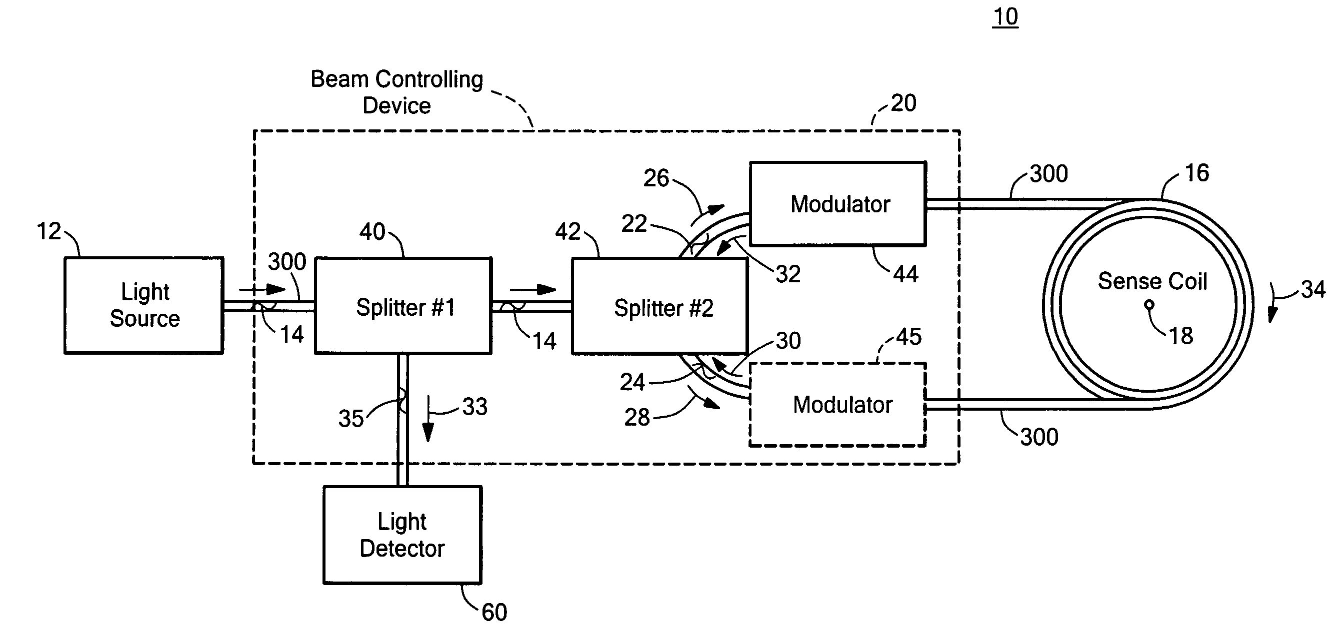
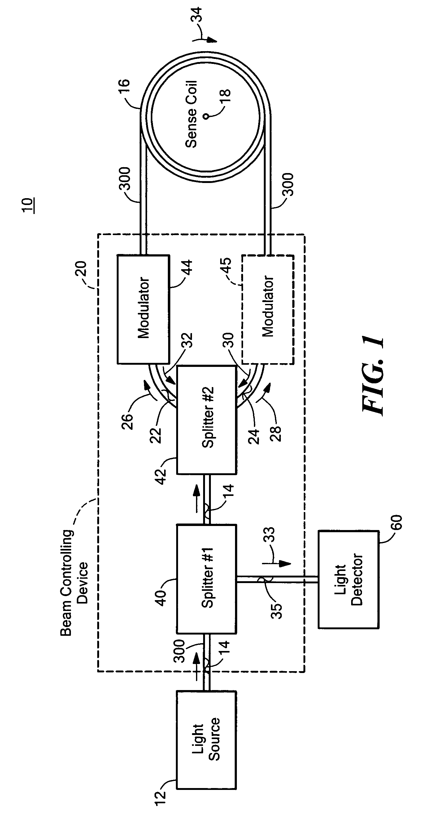
[0039]As discussed in the Background section above, conventional IFOGs suffer from several distinct drawbacks including, inter alia, a limited accuracy, limited sensitivity, limited ability to reduce ARW because of the diameter associated with conventional optical fibers, and limited spectral width light sources. Conventional IFOGs also have a relatively large package diameter (e.g., about three inches in diameter). The sensing coil of conventional IFOGs also utilizes optical fibers with significant bend loss, length loss, sensitivity to ionizing radiation, and thermal sensitivity.
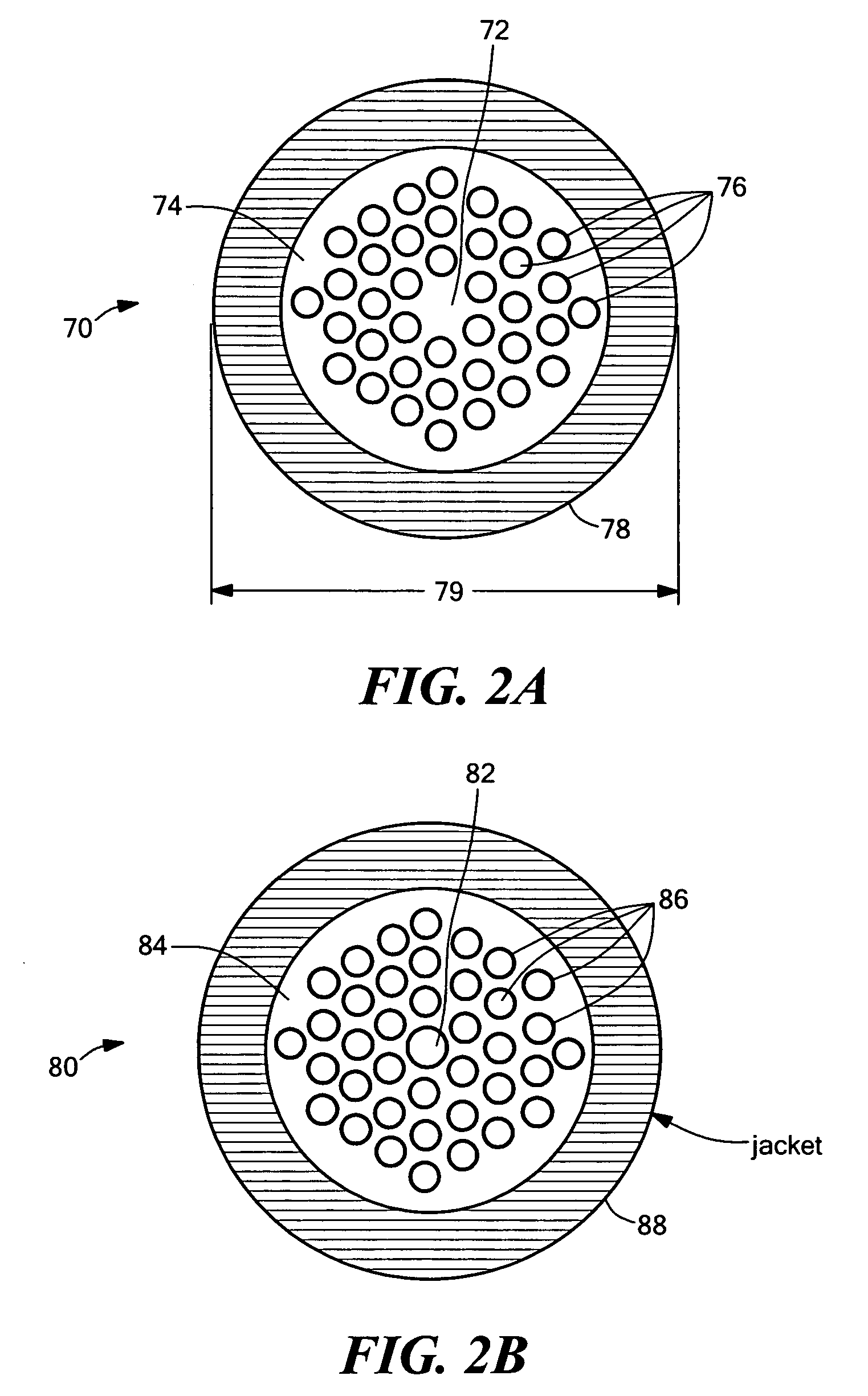
[0040]Pho...


PUM


Abstract

A photonic crystal interferometric optical gyroscope system including a light source for providing a primary beam of light, a photonic crystal sensing coil having a rotational axis, and a beam controlling device configured to split the primary beam into first and second counter-propagating beams in the photonic crystal sensing coil and configured to direct return of the counter-propagating beams wherein the power of the returning counter-propagating beams represents the phase shift between the counter-propagating beams and is indicative of the rate of rotation of the coil about the rotational axis.

Description

RELATED APPLICATIONS[0001]This application claims priority of U.S. Provisional Application No. 60 / 426,264 filed Nov. 13, 2002, incorporated by reference herein.GOVERNMENT RIGHTS[0002]This invention was made with U.S. Government support under Contract No. N00030-01-C-0022 awarded by the U.S. Navy. The Government may have certain rights in the subject invention.FIELD OF THE INVENTION[0003]This invention relates generally to gyroscope systems and more particularly to an improved photonic crystal interferometric fiber optical gyroscope (IFOG) system.BACKGROUND OF THE INVENTION[0004]Gyroscopes may be used to measure an angular change in direction. Conventional IFOGs employ, inter alia, a sensing coil to measure the rate of rotation of the gyroscope. The sensing coil of the IFOG typically includes an optical fiber wound on a mandrel or into a freestanding coil. Light is introduced to the rotating sensing coil and an optical splitter splits the light into two counter-propagating beams. One...

Claims


Application Information

Patent Timeline
Patent Type & Authority Patents(United States)
IPC IPC(8): G01C19/72G02B6/00
CPCG01C19/721
Inventor WILLIG, REINHARDT L.KELLEHER, WILLIAM P.SMITH, STEPHEN P.
Owner CHARLES STARK DRAPER LABORATORY
Why Eureka
Try Eureka