Method and apparatus for treatment of thrombosed hemodialysis access grafts

a technology of hemodialysis and access grafts, applied in the field of interventional radiology, can solve the problems of clot formation, patients may even die, and only offering an average patency of ptfe graft access

Active Publication Date: 2007-02-27
A V MEDICAL TECH +1
View PDF18 Cites 52 Cited by
  • Summary
  • Abstract
  • Description
  • Claims
  • Application Information

AI Technical Summary

Benefits of technology

[0025]It is, therefore, an object of the present invention to provide a method for the treatment of thrombosed hemodialysis access grafts or fistulas defining a shunt positioned between an arterial side and a venous side. The method is achieved by inserting a balloon catheter within the shunt, wherein the balloon catheter includes a distal balloon and at least one infusion aperture located proximally of the distal balloon. Thereafter, the balloon catheter is advanced within an arterial anastomosis at an artery-shunt juncture and the distal balloon is inflated. A thrombolytic agent is then injected through the infusion aperture of the balloon catheter into the shunt to chemically destroy clot material within the shunt, wherein by applying the thrombolytic agent with the distal balloon inflated at the arterial anastomosis the possibility of the clot material moving into the artery is prevented and there is no need to worry about the migration of the clot into the arterial system and the resulting complications. Finally, the inflated distal balloon is pulled toward the venous side, eradicating the arterial plug.

Problems solved by technology

However, PTFE graft access only offers an average patency of 20 months after placement.
Some patients may even die because of lack of access.
Thrombosis, or blood clot formation, is the most common cause of hemodialysis access graft failure.
Graft thrombosis usually results from venous flow obstruction, or stenosis.
A narrowing at this area causes a slow down or obstruction of blood flow, resulting in the formation of the thrombus within the graft.
Mechanical thrombectomy devices are expensive and often require capital investment.
However, residual thrombus may occur with the device, and it cannot be used to treat the arterial plug.
One concern with this device, however, is the amount of blood aspirated during the procedure (50–150 mL), which could be problematic for chronically anemic patients.
Although this design has shown some utility, it does not offer guidewire compatibility.
The basic technique for recanalization of hemodialysis access grafts using these devices often consists of a crossover catheterization requiring, unfortunately, multiple equipment.
Despite many advantages, traditional mechanical thrombolytic devices often exhibit significant drawbacks.
Some devices are large (8-French or more) and perform poorly in curved vessels, limiting their use in hemodialysis access.
Residual adherent clot is a considerable problem with some mechanical devices.
Many devices do not remove the macerated clot and it may be embolized into the lungs.
A great number of the available devices cannot be used over-the-wire.
The technique is working very well, however, the whole length of the graft cannot be cleared or visualized.
Unfortunately, injection of a contrast material into the graft cannot be safely performed before flow in the graft is reestablished.
In some cases, flow cannot be established and the operator cannot tell what is the cause for the lack of success.
In particular, current techniques offer no mechanism for the application of thrombolytic solutions and contrast solutions within the occluded graft due to concerns relating to the migration of clots into the arterial system.
This is undesirable.

Method used


Image

  • Method and apparatus for treatment of thrombosed hemodialysis access grafts
  • Method and apparatus for treatment of thrombosed hemodialysis access grafts
  • Method and apparatus for treatment of thrombosed hemodialysis access grafts

Examples


Embodiment Construction

[0036]The detailed embodiments of the present invention are disclosed herein. It should be understood, however, that the disclosed embodiments are merely exemplary of the invention, which may be embodied in various forms. Therefore, the details disclosed herein are not to be interpreted as limited, but merely as the basis for the claims and as a basis for teaching one skilled in the art how to make and / or use the invention.

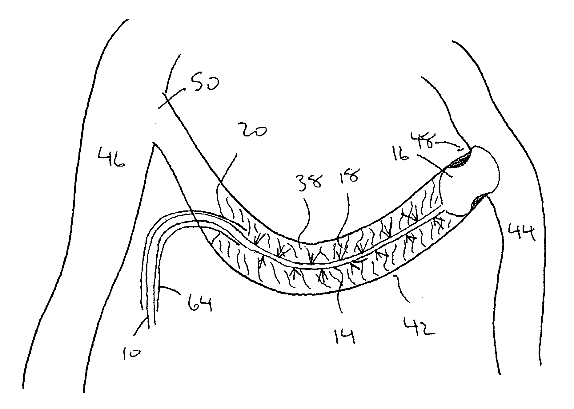
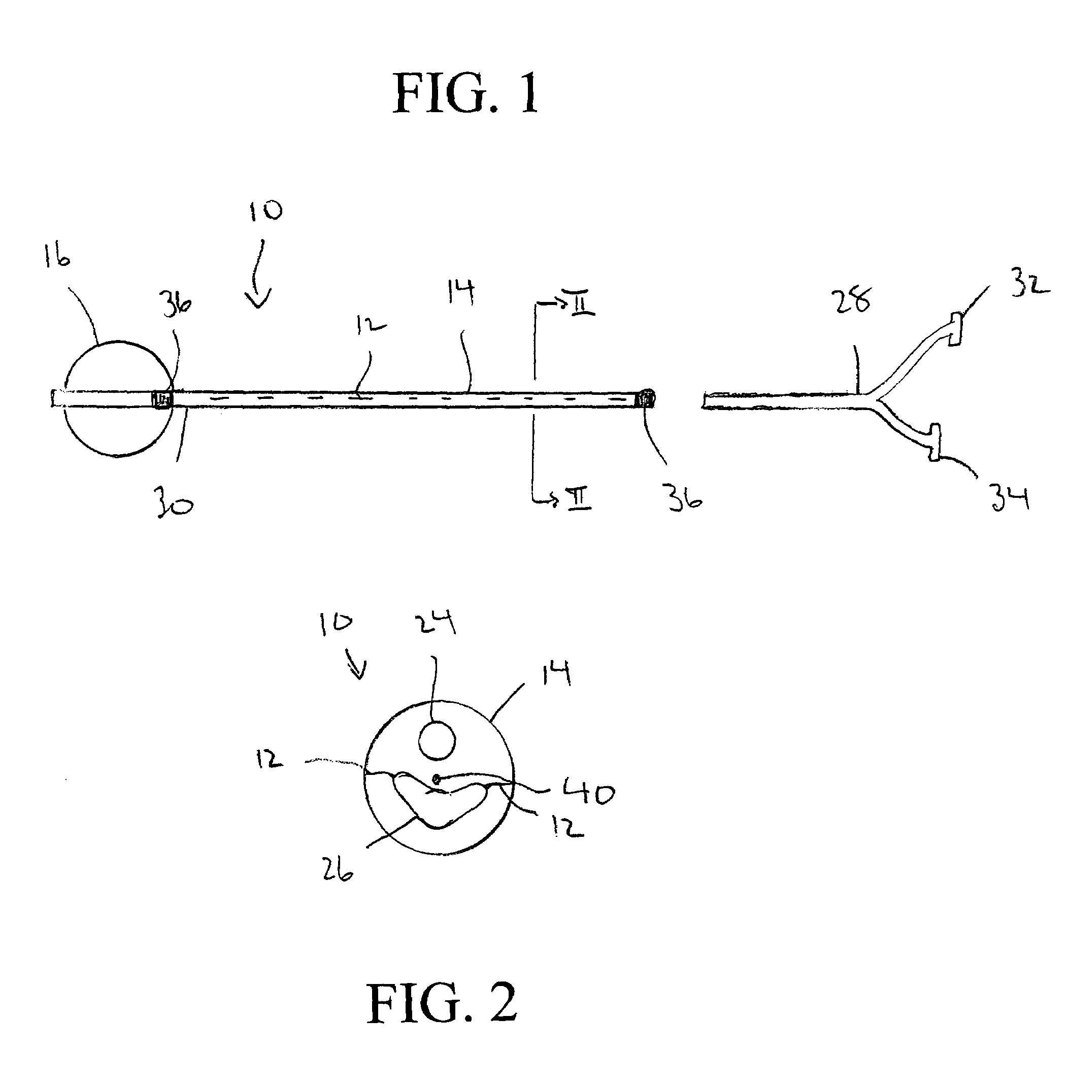
[0037]With reference to FIGS. 1, 2, 3a and 3b, a balloon catheter 10 with proximal infusion apertures 12 for the injection of thrombolytic agents or contrast materials is disclosed. The present balloon catheter 10 is preferably designed for use in dialysis access declotting, although those skilled in the art will appreciate that it may be used for a variety of applications. In accordance with a preferred embodiment of the present invention, the catheter 10 is approximately 40 cm to approximately 60 cm long, although those skilled in the art will appreciate that ot...


PUM


Abstract

A method for the treatment of thrombosed hemodialysis access grafts or fistulas defining a shunt positioned between an arterial side and a venous side is achieved by inserting a balloon catheter within the shunt, wherein the balloon catheter includes a distal balloon and at least one infusion aperture located proximally of the distal balloon. Thereafter, the balloon catheter is advanced within an arterial anastomosis at an artery-shunt juncture and the distal balloon is inflated. A thrombolytic agent is then injected through the infusion apertures of the balloon catheter into the shunt to chemically destroy clot material within the shunt, wherein by applying the thrombolytic agent with the distal balloon inflated at the arterial anastomosis the possibility of the clot material moving into the artery is prevented and there is no need to worry about the migration of the clot into the arterial system and the resulting complications. Finally, the inflated distal balloon is pulled toward the venous side, eradicating the arterial plug. A balloon catheter for use in accordance with the present invention is also disclosed.

Description

CROSS REFERENCE TO RELATED APPLICATIONS[0001]This application is based upon U.S. Provisional Patent Application Ser. No. 60 / 505,665, filed Sep. 24, 2003, entitled “Dialysis Access Thrombectomy Catheter”.BACKGROUND OF THE INVENTION[0002]1. Field of the Invention[0003]The present invention relates to the field of interventional radiology. More particularly, the invention relates to a method and apparatus for the reconstruction of a flow path within a vascular conduit. The invention further relates to embolectomy and thrombectomy, including treatment of thrombosed hemodialysis access grafts or fistulas.[0004]2. Description of the Prior Art[0005]Life-sustaining access to hemodialysis is one of the leading causes for hospital admission. More than 80% of the patient population undergoing hemodialysis treatments have a PTFE graft access. However, PTFE graft access only offers an average patency of 20 months after placement.[0006]If one considers that the arterial and venous anatomy is typi...

Claims


Application Information

Patent Timeline
Patent Type & Authority Patents(United States)
IPC IPC(8): A61M31/00A61M29/00A61F2/958A61MA61M25/00
CPCA61M25/0029A61M25/007A61M25/10A61M25/0032A61M25/0023A61M2025/1052
Inventor TAL, MICHAEL G.
Owner A V MEDICAL TECH
Why Eureka
Try Eureka