
Method and system for video capture of vehicle information

a technology for vehicle information and video capture, applied in the field of video capture devices, can solve the problems of inability to use images, degradation or loss of parts of original video images, and high cost of analog camera and capture board methods, so as to improve the appreciation of contributions to the art, the effect of high performan

Active Publication Date: 2007-02-27
SPX CORP
View PDF74 Cites 20 Cited by
  • Summary
  • Abstract
  • Description
  • Claims
  • Application Information

AI Technical Summary

Benefits of technology

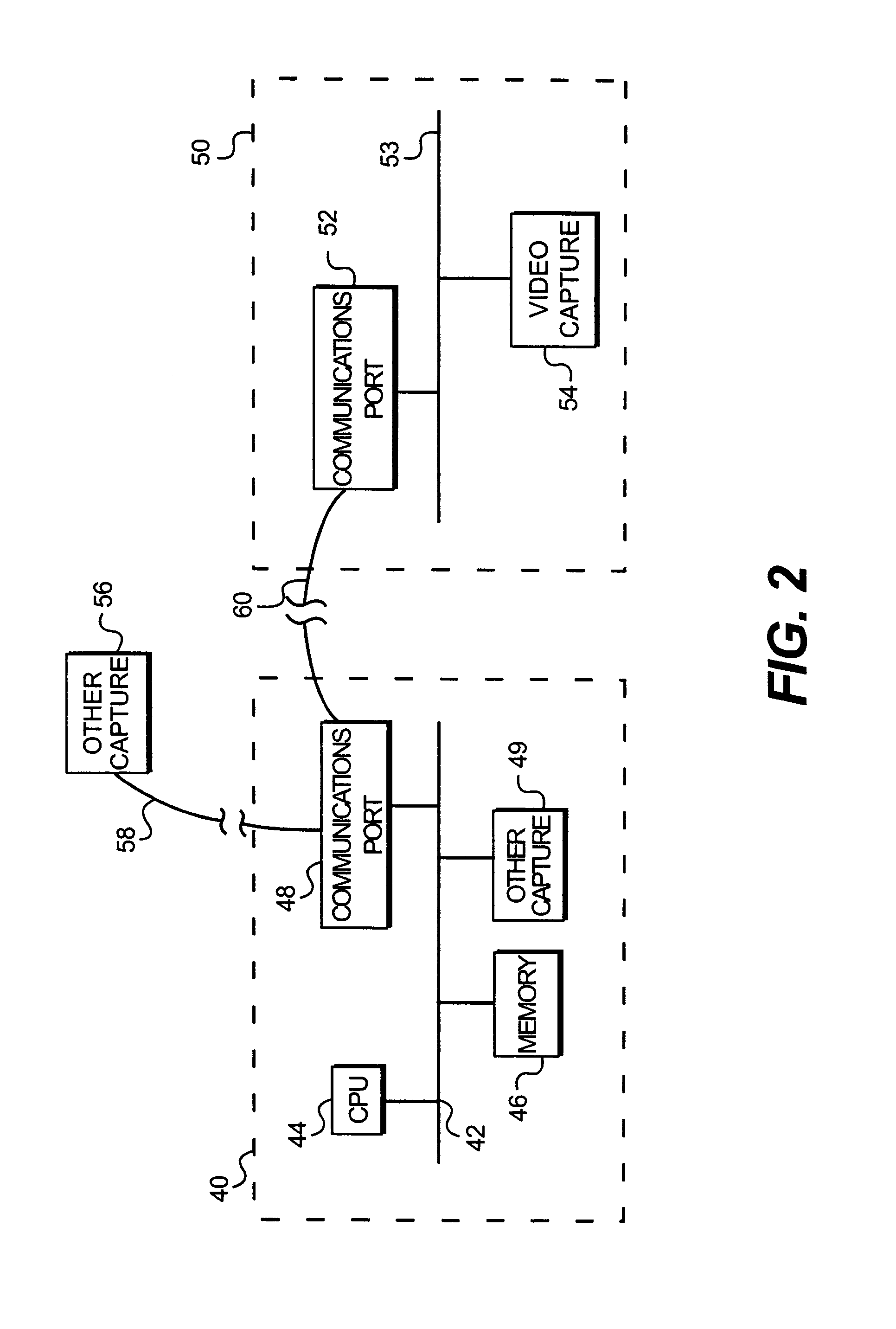
[0006]It is therefore a feature and advantage of the present invention to provide a novel video capture system as herein disclosed In accordance with one embodiment of the present invention, a system for managing visual images of vehicles includes a first digital video image collector positioned to capture a first data file that is representative of a visual image of at least one feature of a first vehicle moving on a roadway, The first digital video image collector includes: (1) a first communications port; (2) a computing device having a processor, a memory, and (3) a second communications port; a first communications link between the first communications port and the second communications port. A first information collection device is in communication with the computer and positioned to capture speed, acceleration, and / or emissions data corresponding to the first vehicle. Preferably, the first communications port an / or the first communications link is capable of transferring data at a transfer rate substantially equal to at least one of 100, 200, and 400 megabits per second and / or substantially complies with the Institute for Electrical and Electronics Engineers (IEEE) 1394 Standard for a High Performance Serial Bus, vehicle.
[0007]Optionally, the system also includes a second digital video image collector positioned to capture a second data file that is representative of a visual image of at least one feature of a second vehicle moving on a roadway. The second digital camera includes a third communications port and a second communications link between the third communications port and the first digital video image collector. Preferably, the second information collection device is further positioned to capture at least one of speed, acceleration, and emissions data corresponding to the second vehicle. Also preferably, this system includes a second information collection device positioned to capture at least one of speed, acceleration, and emissions data corresponding to the second vehicle. The third communications port and / or the third communications link should be capable of transferring data at a transfer rate substantially equal to at least one of 100, 200, and 400 megabits per second, and it should substantially comply with the IEEE 1394 Standard for a High Performance Serial Bus.
[0008]Optionally, the system also includes an illumination source positioned to provide illumination directed to the at least one feature of the first vehicle.
[0009]In accordance with an alternate embodiment, a method of capturing and managing vehicle images includes the steps of: (1) using a first video capture device to collect a first digital image of at least one feature of a first vehicle; (2) using a data collection device to collect first data representative of at least one of speed, acceleration, and emissions of the first vehicle; and (3) delivering the first digital image and the first data to a computer program memory via at least one communications link. Preferably, the delivering step is performed at a transfer rate substantially equal to at least one of 100, 200, and 400 megabits per second, and / or it is the delivering step is performed via a serial connection that substantially complies with the IEEE 1394 Standard for a High Performance Serial Bus.
[0010]There have thus been outlined the more important features of the invention in order that the detailed description thereof that follows may be better understood, and in order that the present contribution to the art may be better appreciated. There are, of course, additional features of the invention that will be described below and which will form at least part of the subject matter of the claims appended hereto.
[0011]In this respect, before explaining at least one embodiment of the invention in detail, it is to be understood that the invention is not limited in its application to the details of construction and to the arrangements of the components set forth in the following description or illustrated in the drawings. The invention is capable of other embodiments and of being practiced and carried out in various ways. Also, it is to be understood that the phraseology and terminology employed herein, as well as the abstract included below, are for the purpose of description and should not be regarded as limiting in any way.

Problems solved by technology

In some compression techniques, and especially techniques that start with analog images, the method of compression often results in degradation or loss of part of the original video image.
In such a situation, if the license plate number and / or state is not legible in the stored image, the image cannot be used.
In addition, many applications require more than just a license plate number, such as information relating to vehicle manufacturer, color, and / or type, which are all additional items of information which can be lost in the compression process.
In addition, the method of using an analog camera and capture board is expensive, as many pieces of equipment are required to accomplish the result.
Further, many of the prior art video capture cards generally can handle only one camera.
Accordingly, they are not desirable in applications where multiple cameras are required, such as in areas where multiple cameras are used to collect data across multiple lanes of a roadway.

Method used


Image

  • Method and system for video capture of vehicle information
  • Method and system for video capture of vehicle information
  • Method and system for video capture of vehicle information

Examples


Embodiment Construction

Embodiments of the Invention

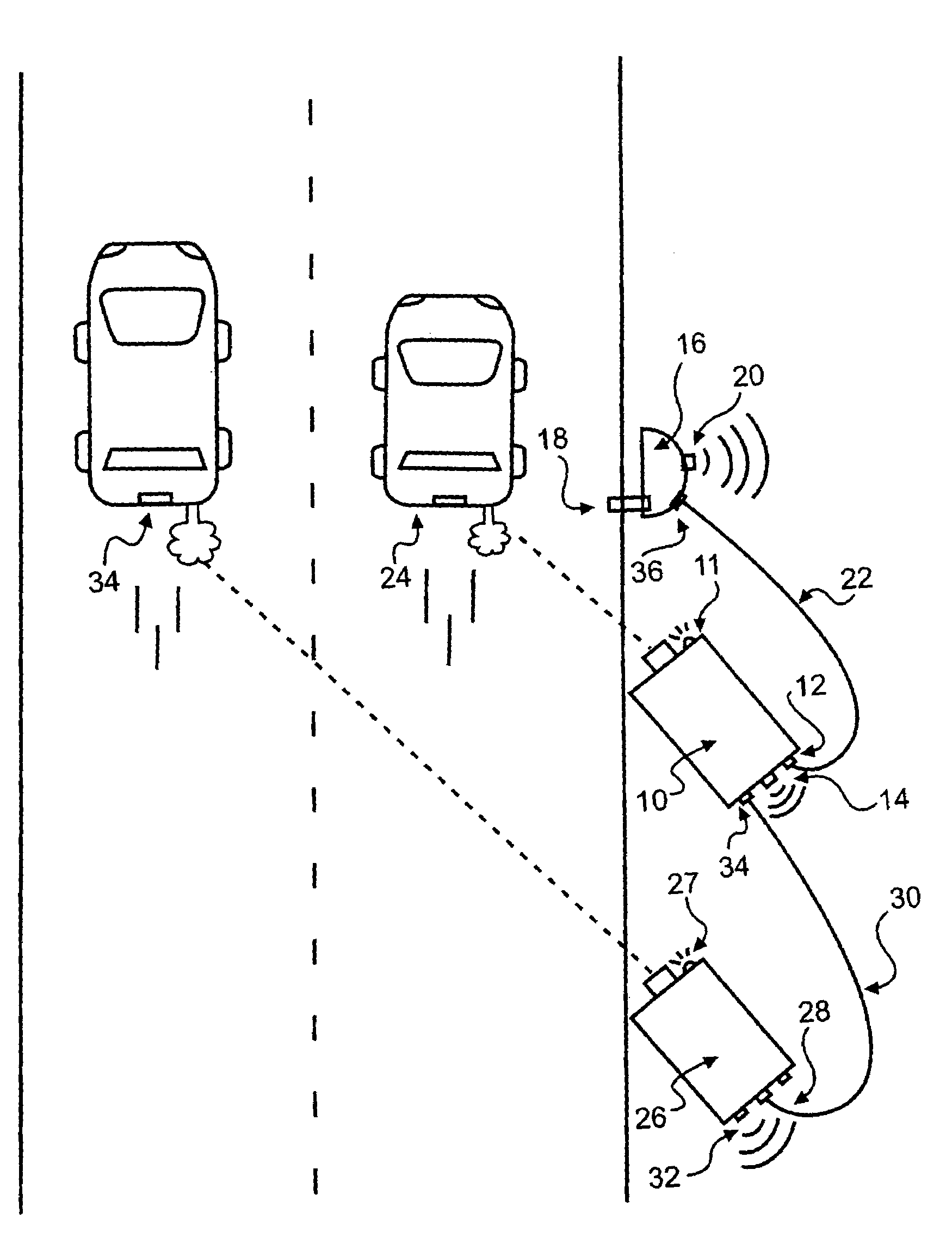
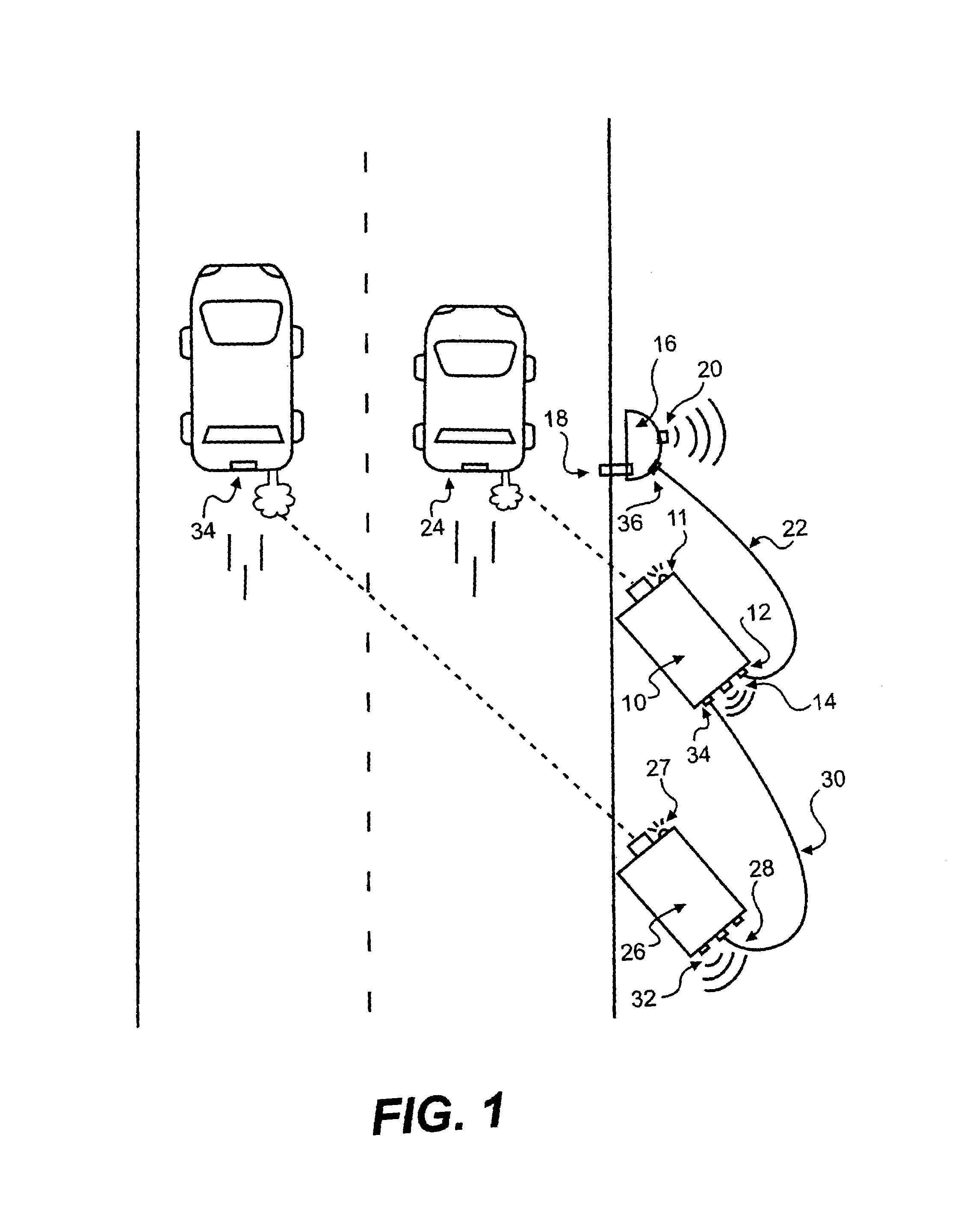
[0017]A preferred embodiment of the present invention provides an improved method and system for capturing and managing video images corresponding to one or more features of a vehicle or vehicles in connection with other data relating to the vehicle or vehicles. A preferred embodiment of the present inventive system is illustrated in FIG. 1. Referring to FIG. 1, a first digital video capture device 10 is positioned along, near, or over a roadway and is positioned to capture a digital image of one or more features of a vehicle 24. Such features preferably include the vehicle's license plate number and state, and they may also include additional features, such as vehicle make, model, color, registration date, and / or inspection sticker data. Preferably, the position of the video capture device provides a skew angle to the vehicle features of not more than approximately 30 degrees. Other angles may be used, but they may not provide picture qualities that are ...


PUM


Abstract

A system for collecting and managing information relating to vehicles includes a digital image collection system positioned to capture an image of a vehicle travelling along a roadway. The captured images are delivered to a computer program memory via a communications link at a transfer rate substantially equal to 100, 200, and / or 400 megabits per second. A second device collects additional information relating to the vehicle, such as the vehicle's speed, acceleration, and / or emissions data, and also delivers such information to the memory. Alternatively, two or more video capture devices may be connected in series via communications links that are all capable of transmitting data at rates substantially equal to 100, 200, and / or 400 megabits per second, such that the images collected by all of the capture devices are delivered to the memory.

Description

FIELD OF THE INVENTION[0001]The present invention relates generally to video capture devices. More particularly, the present invention relates to a method and system for capturing, storing, and transmitting visual images of elements of vehicles for use in connection with emissions data collection, law enforcement, and / or transportation systems planning.BACKGROUND OF THE INVENTION[0002]The collection of visual images of vehicles as they move along a roadway has been found to be useful in an increasing number of applications. For example, the collection of visual images of vehicle license plates, along with images of vehicle types and / or colors, is useful in law enforcement to identify vehicles that exceed a speed limit and / or who otherwise violate traffic-related laws. When used in conjunction with other information, such as emissions data, vehicle inspection due dates, and other information, such images can be used to determine an individual vehicle's compliance with requirements su...

Claims


Application Information

Patent Timeline
Patent Type & Authority Patents(United States)
IPC IPC(8): G08G1/017G06T7/20G07B15/02G08G1/054
CPCG08G1/054G07B15/00
Inventor DIDOMENICO, JOHNKYLE, PAUL F.
Owner SPX CORP
Learn More