Drying device for drying a gas

a drying device and gas technology, applied in drying, light and heating equipment, furnace types, etc., can solve the problems of disadvantages of high energy consumption in this drying plant, the device is still relatively large, and the bulk material of this kind can have too much moisture for processing, etc., and achieve the effect of low energy consumption

Inactive Publication Date: 2007-03-06
ARBEITER PETER
View PDF15 Cites 38 Cited by
  • Summary
  • Abstract
  • Description
  • Claims
  • Application Information

AI Technical Summary

Benefits of technology

[0009]An important object of the invention is to provide a drying device of the type mentioned in the beginning which means of which a low dew point temperature of the dried gas and a low energy consumption can be achieved.
[0011]By means of the air conveyor for ambient air, by which the ambient air can be conveyed via the ambient-air input line through a respective cooling branch in its passive state and flows out through the ambient-air output line after flowing through the cooling branch, the respective passive cooling branch can be thawed and regenerated in a simple manner.
[0013]Further, the drying device preferably comprises at least one gas-gas heat exchanger having a first channel through which the gas to be dried is guided before being guided through one of the cooling branches and a second channel through which the gas to be dried is guided after being guided through one of the cooling branches. In this way, a highly energy-saving drying device can be provided.
[0014]In an advantageous embodiment form of the invention, in the passive state of a respective cooling branch, the second channel of the gas-coolant heat exchanger of this cooling branch, at least for a time, forms a condenser for the coolant circulating in the coolant circuit. A particularly efficient regeneration of the passive cooling branch is achieved in this way.
[0015]A drying device, according to the invention, can be constructed so as to be robust, durable and, therefore, economical.

Problems solved by technology

After a certain storage period or after production, bulk material of this kind can have too much moisture for processing, e.g., in extruders or injection molding machines, particularly when it is hydroscopic.
This drying plant is disadvantageous due to the required servicing because the adsorbent material must constantly be changed in a time-consuming manner and the total energy consumption of the device is still relatively high.
Accordingly, the compressed air supplied to the molecular sieve dryer has a dew point of 3° C. The regular servicing of the compressed-air compressor and the high energy consumption are disadvantageous in this drying plant.
Among the disadvantages in this device is the fact that the additional moisture absorbed by the partial flow in the passive cooling branch leads to a faster icing of the active cooling branch so that more frequent switching processes are required between the branches.
This decreases the overall efficiency of the plant.

Method used


Image

  • Drying device for drying a gas
  • Drying device for drying a gas
  • Drying device for drying a gas

Examples


Embodiment Construction

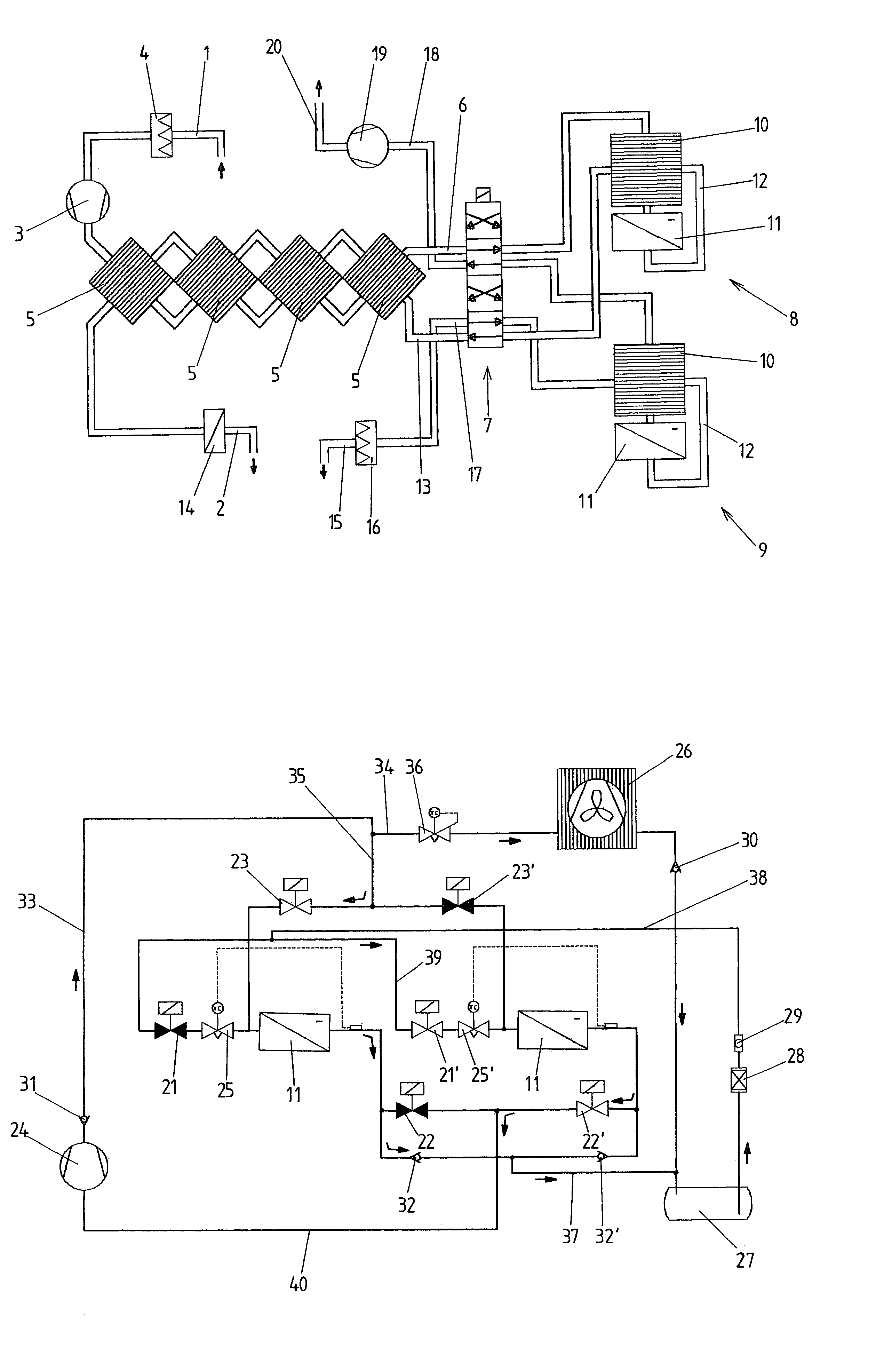
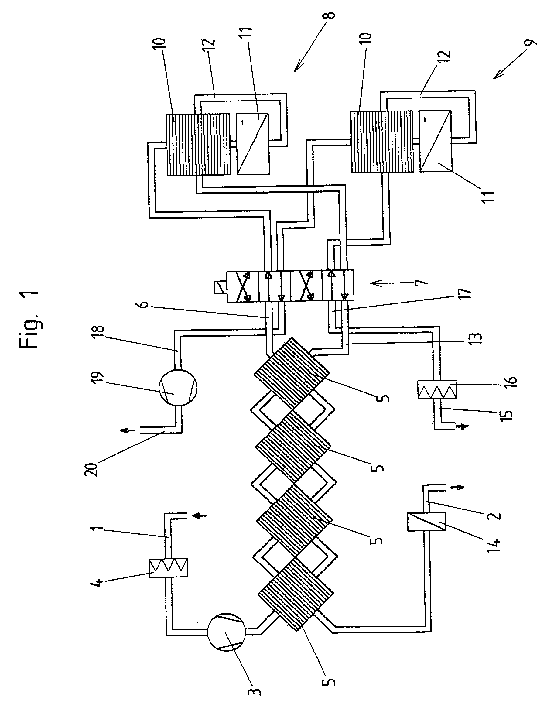
[0022]An embodiment example of a drying device according to the invention is shown schematically in FIG. 1 without the coolant circuit. The gas to be dried, in particular air, is supplied through a gas input line 1 and, after being dried, flows through a gas output line 2. The gas is guided through the drying device by means of a gas conveyor 3, arranged in the present example in the region of the gas input line 1, in the form of a ventilator or blower. Further, an air filter 4 is arranged in the gas input line 1 in front of the gas conveyor 3. The gas to be dried is guided further through at least one gas-gas heat exchanger 5. Preferably, a plurality of such gas-gas heat exchangers 5 or a multiple-stage gas-gas heat exchanger is provided. An initial cooling of the gas to be dried is carried out in the gas-gas heat exchanger 5, wherein the dew point of the gas to be dried is preferably not yet reached, so that there is still no condensation in the gas-gas heat exchanger. When using ...


PUM


Abstract

A drying device for drying a gas comprises parallel cooling branches, at least one of which is in its active state at any given time. A gas-coolant heat exchanger arranged in each of the cooling branches has a first channel through which the gas to be dried flows in the active state of this cooling branch and a second channel which, in the active state of this cooling branch, forms an evaporator for a coolant circulating in at least one coolant circuit. The drying device further comprises an ambient-air input line, an ambient-air output line and an ambient-air conveyor. In the passive state of a respective cooling branch, the ambient-air input line and the ambient-air output line are connected, at least for a time, with this cooling branch by the switching device and the ambient-air conveyor conveys ambient air through the first channel of the gas-coolant heat exchanger arranged in this cooling branch.

Description

CROSS-REFERENCE TO RELATED APPLICATION[0001]This application claims priority of Austrian Application No. A 745 / 2004, filed Apr. 29, 2005, the complete disclosures of which are hereby incorporated by reference.BACKGROUND OF THE INVENTION[0002]a) Field of the Invention[0003]The invention is directed to a drying device for drying a gas, particularly a gas that is guided in a circuit through a drying vessel of a drying plant, which drying vessel receives material to be dried, with a gas input line for supplying the gas to be dried and with a gas output line for discharging the dried gas, and with parallel cooling branches which can be switched by a switching device between an active state, in which the gas to be dried flows through the cooling branch and cold-drying of the gas is carried out in the cooling branch, and a passive state, wherein at least one of the cooling branches is in its active state at a given time, and wherein a gas-coolant heat exchanger arranged in each of the cool...

Claims


Application Information

Patent Timeline
Patent Type & Authority Patents(United States)
IPC IPC(8): F26B3/00F26B3/06F26B23/00F26B21/00F26B21/08
CPCF26B21/086Y02P70/10
Inventor ARBEITER, PETER
Owner ARBEITER PETER
Why Eureka
Try Eureka