Apparatus for measuring two-dimensional displacement
a two-dimensional displacement and apparatus technology, applied in the field of apparatus for measuring two-dimensional displacement, can solve the problems of increasing the risk of personnel outflow, and difficulty in meeting the requirement for being used in high-precision systems. , to achieve the effect of easy to obtain periodic wave interference signals
- Summary
- Abstract
- Description
- Claims
- Application Information
AI Technical Summary
Benefits of technology
Problems solved by technology
Method used
Image
Examples
first embodiment
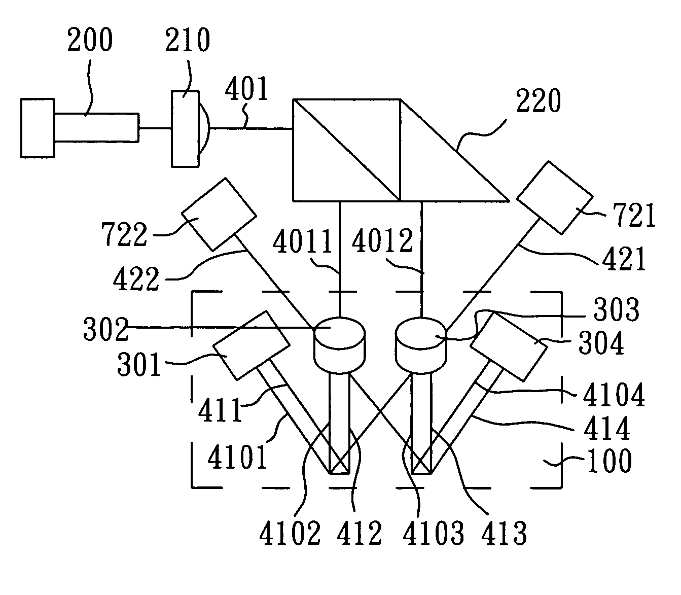
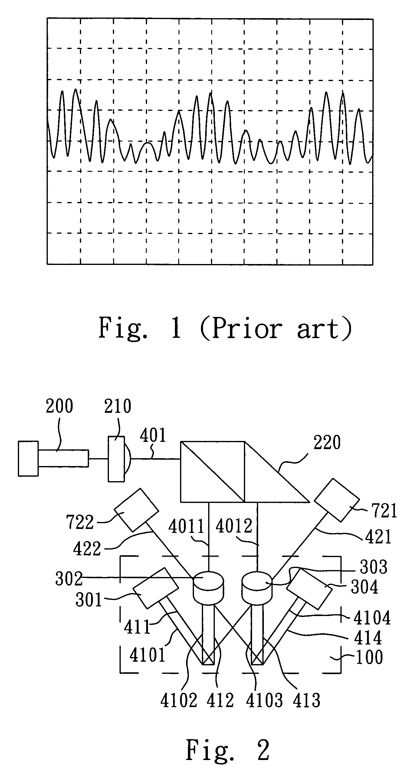
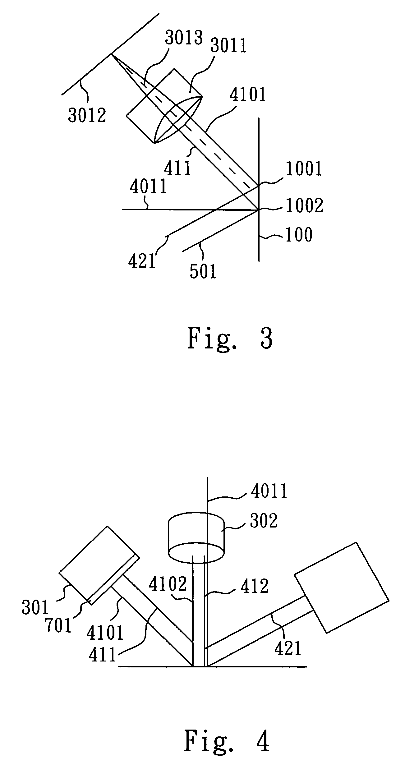
[0029]FIG. 5 schematically illustrates the aforesaid interference optical dephasing module 721. With reference to FIGS. 2 and 5 for the following description, because the second diffracted beam 421 reflected by the two-dimensional diffraction unit 100 contains information about displacement in the X direction, the second diffracted beam 421 is dephased by means of the interference optical dephasing module 721 to obtain periodic wave signals of displacement information in the X direction so that a two-dimensional displacement is measured based on the periodic wave signals. The interference optical dephasing module 721 comprises a beam splitter 7211 and polarisers 731, 732, the polarisers 731, 732 being disposed on the optical paths formed by the beam splitter 7211 respectively with an angle of 45° between the optical axes thereof. After the second diffracted beam 421 enters the interference optical dephasing module 721, two signal beams 4211, 4212, which are split by means of the bea...
second embodiment
[0030]FIG. 6 schematically illustrates the interference optical dephasing module 721. With reference to FIGS. 2 and 6 for the following description, the interference optical dephasing module 721 comprises beam splitters 7222, 7223, 7224 and polarisers 733, 734,735736 having an angle of 45° between the optical axes thereof. After the second diffracted beam 421 enters the interference optical dephasing module 721, two signal beams 4213, 4214 are split by means of the beam splitter 7222. Further, the signal beam 4213 is split by means of the beam splitter 7223 to form two signal beams 4215, 4216 while the signal beam 4214 is split by means of the beam splitter 7224 to form two signal beams 4217, 4218. Accordingly, the four signal beams 4215, 4216, 4217, 4218 are formed after the second diffracted beam 421 enters the interference optical dephasing module 721, passing through the polarisers 733, 734, 735, 736, respectively.
[0031]In sum, the second-order diffracted beams generated as a re...
PUM
 Abstract
Description
Claims
Application Information
 - R&D
- Intellectual Property
- Life Sciences
- Materials
- Tech Scout
- Unparalleled Data Quality
- Higher Quality Content
- 60% Fewer Hallucinations
Browse by: Latest US Patents, China's latest patents, Technical Efficacy Thesaurus, Application Domain, Technology Topic, Popular Technical Reports.
© 2025 PatSnap. All rights reserved.Legal|Privacy policy|Modern Slavery Act Transparency Statement|Sitemap|About US| Contact US: help@patsnap.com


