
Wavelength division multiplexing optical transmission system using a spectral inversion device

a wavelength division multiplexing and optical transmission technology, applied in wavelength-division multiplex systems, optical transmission, multi-component communication, etc., can solve the problems of insufficient use of dcf fibres, inability to compensate the dispersion over inability to achieve optimal solutions for the whole signal band, etc., to achieve low reception errors and easy implementation in the system

Active Publication Date: 2007-03-06
GOOGLE LLC
View PDF19 Cites 4 Cited by
  • Summary
  • Abstract
  • Description
  • Claims
  • Application Information

AI Technical Summary

Benefits of technology

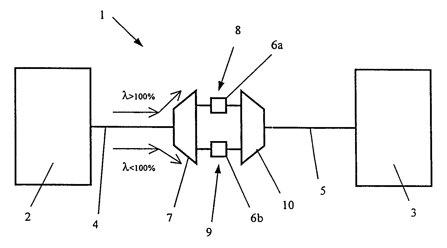
[0034]The applicant has found that this problem can be solved by using the spectral inversion technique in an optical transmission system with dispersion of alternate sign. The applicant has verified that, by using a spectrum inverter together with optical fibres with alternating dispersion, it is possible to obtain a very wide wavelength band for transmission at high bit rates, for example at 40 Gbit / s, with very low reception errors for the transmitted channels. The use of a spectrum inverter is advantageous, in particular, for WDM systems with alternating dispersion which are already installed, since it can easily be implemented in the system.

Problems solved by technology

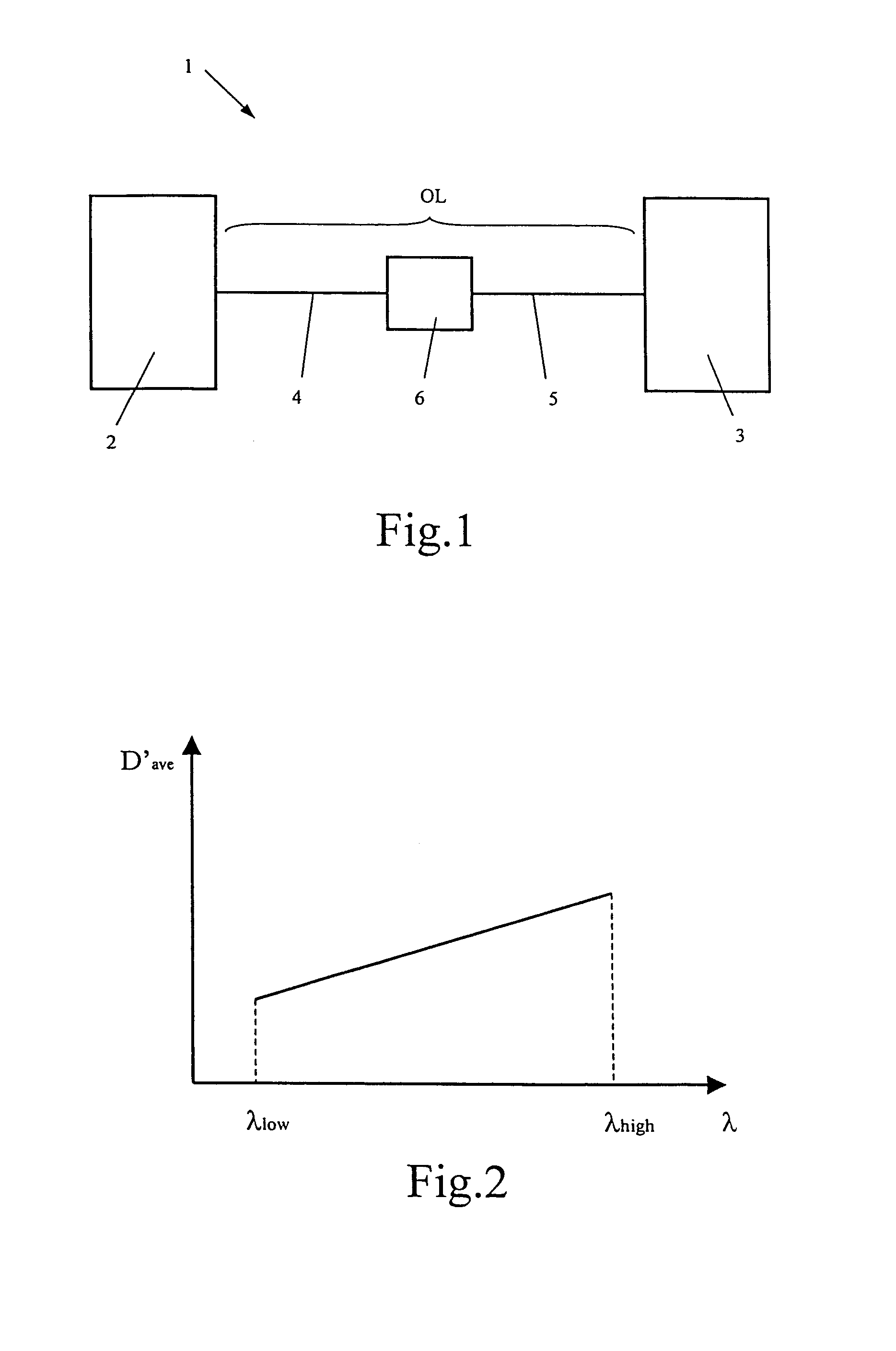
Since the chromatic dispersion is dependent on the wavelength, with a practically linear relationship having a generally non-zero slope in the transmission window around 1.5 μm, different channels accumulate different dispersion levels, and it therefore becomes more difficult to compensate the dispersion over the whole signal band.
This problem is particularly important in high bit rate systems (>10 Gbit / s), for which the dispersion compensation has to be carried out very accurately.
According to the applicant, the use of DCF fibres which can simultaneously compensate the dispersion and the slope of the dispersion over the whole signal band is not an optimal solution, since these fibres, having very specific dispersion characteristics, are rather difficult to produce and therefore very expensive.
Moreover, in previously installed systems this solution would require the replacement of all the DCF fibres of the system, with a considerable increase in cost.
The use of optical fibre gratings also has drawbacks, such as an imperfectly linear variation of dispersion with respect to wavelength, and a marked sensitivity to temperature variations, which makes it necessary to use suitable carefully designed packages in which the operating temperature is controlled.
This method is not adequate for a case where a plurality of channels is transmitted at different wavelengths.
According to the applicant, this technique for compensating the second-order dispersion effects is rather complicated and costly, since a multi-channel phase conjugator consisting of as many phase conjugators as there are channels in the system is a very complex device, particularly for systems with many channels.
It is also disadvantageous when the number of channels in a system is increased, as a result of an increase in the required transmission capacity: in this case, a multi-channel conjugator of this type would have to be redesigned and / or replaced to allow for the introduction of the new channels.
The applicant has verified that, in a high transmission rate WDM system, it is possible that dispersion compensation using optical fibres with alternating dispersion, with a non-zero slope of the average dispersion with respect to the wavelength, will not permit satisfactory reception of a large part of the WDM signal, even if it is carried out with additional post-compensation optical fibres dedicated to each channel before the receiver.
According to the applicant, these channels are more sensitive to distortion due to non-linear effects (such as XPM and SPM) which occur in the course of transmission along the optical line, so that a linear compensation of the dispersion before the receiver is no longer sufficient to recover an acceptable shape of the pulses.

Method used


Image

  • Wavelength division multiplexing optical transmission system using a spectral inversion device
  • Wavelength division multiplexing optical transmission system using a spectral inversion device
  • Wavelength division multiplexing optical transmission system using a spectral inversion device

Examples


example 1

[0133]The launch of under-compensated channels in a wavelength range from 1550 nm to 1561.2 nm, in a system with the characteristics described above, was simulated. The power per channel was 8 dBm. The pulses had a time interval of 25 ps and a width of 3 ps. Before input into the spans of optical fibres with alternating dispersion, a pre-compensation of +50 ps2 was added to all the channels. The simulation was conducted without the spectrum and wavelength conversion device. The performance of the system was evaluated by determining the quantity of post-compensation to be applied, for all the channels, at the ends of the five spans of fibre. In particular, what is known as the “eye-opening”, in other words the difference between the least powerful “1” bit and the most powerful “0” bit, was measured, for each transmitted channel and with different values of post-compensation, at the transmission station and at the receiving station. The difference between the transmitted eye-opening a...

example 2

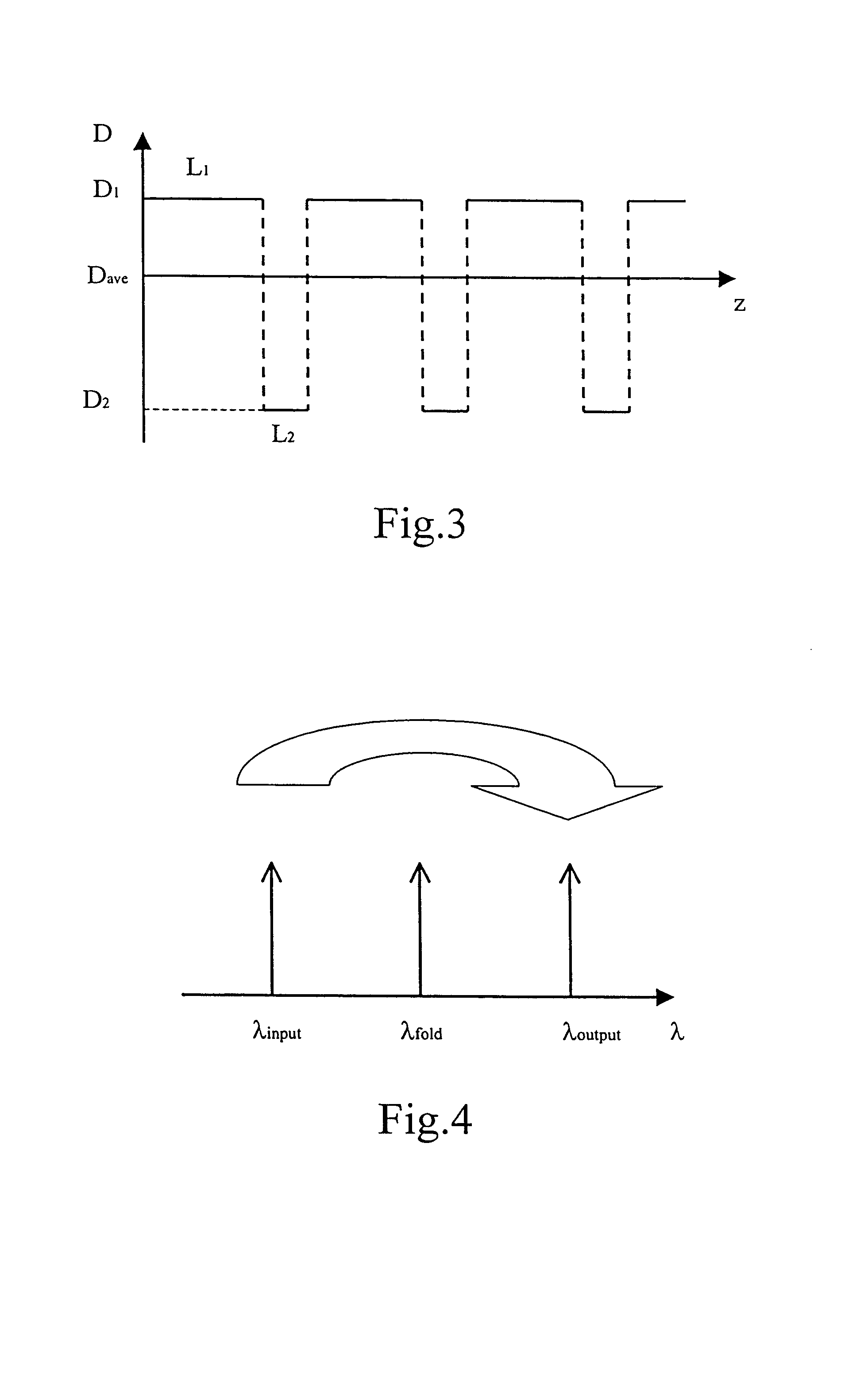
[0134]The simulation described with reference to Example 1 was repeated, with a spectrum and wavelength conversion device inserted after the fourth span of pairs of optical fibres. The folding radiation of the device had a wavelength of 1561.6 nm. Downstream of the conversion device, the channels had wavelengths in the range from 1562 nm to 1573.2 nm. FIG. 11 shows the result of the simulation. The wavelengths shown on the horizontal axis correspond to the wavelengths of the transmitted channels (upstream of the conversion). The level curves show, with the respective kind of line, the same maximum penalties as those shown in Example 1. It may be noted that the useful bandwidth for obtaining a penalty level less than or equal to 0.5 dB shown in FIG. 11 extends through the whole region from 1550 to 1561.2. As can be seen more clearly from FIG. 11, it can also extend into values above 1561.2. This corresponds to a wavelength band of more than 11 nm. This means that it is possible to co...

example 3

[0135]The simulations described with reference to Examples 1 and 2 were repeated, with the average power per channel raised to 10 dBm. In the case without a conversion device, the 0.5 dB maximum penalty band was found to be further confined to a wavelength region between 1550 and 1552 nm. In other words, for a typical channel spacing of 200 GHz (1.6 nm) (at 40 Gbit / s), a maximum of two channels with wavelengths above 1550 nm can be compensated while maintaining a penalty level less than or equal to 0.5 dB. With the conversion device, a 0.5 dB maximum penalty band of approximately 11 nm could still be obtained. In other words, for a typical channel spacing of 200 GHz (1.6 nm) (at 40 Gbit / s), seven to eight channels having wavelengths above 1550 nm can be compensated while maintaining a penalty level less than or equal to 0.5 dB.


PUM


Abstract

A WDM system includes a transmission station, a receiving station, a first optical path and a second optical path. The first optical path includes a first section and a second section, the second section being capable of compensating at least partially the dispersion accumulated by a series of optical channels along the first section. The series of channels includes at least a first plurality of channels having an average dispersion of the same sign in the first optical path. The system also includes at least a first conversion device, capable of inverting the spectrum and modifying the wavelength of at least the first plurality of channels, to produce a second plurality of channels having an average chromatic dispersion of the same sign in the second optical path.

Description

CROSS REFERENCE TO RELATED APPLICATIONS[0001]This application claims the benefit of U.S. Provisional Application Ser. No. 60 / 309,480, filed Aug. 3, 2001, the content of which is incorporated herein by reference, and claims the right to priority based on European Application No. 01118289.6, filed Jul. 30, 2001.BACKGROUND OF THE INVENTION[0002]1. Field of the Invention[0003]The present invention relates to the compensation of chromatic dispersion in a wavelength division multiplexing (WDM) optical transmission system. In particular, the present invention relates to compensation of the dependence of the chromatic dispersion on wavelength by means of a spectral inversion device.[0004]The following definitions are used in the remainder of the description:[0005]Optical channel: modulated signal on an optical carrier having a given central frequency. The modulated signal has a frequency much lower than the central frequency of the optical carrier. For the purposes of the present descriptio...

Claims


Application Information

Patent Timeline
Patent Type & Authority Patents(United States)
IPC IPC(8): H04J14/02H04B10/04H04B10/06H04B10/12H04B10/18H04B10/135
CPCH04B10/2531H04B2210/258
Inventor CARBONE, FABRIZIOSOCCI, LUCIANOROMAGNOLI, MARCO
Owner GOOGLE LLC
Learn More