Electron accelerator and radiotherapy apparatus using same

a radiation medical treatment and accelerator technology, applied in the field of electromagnetic accelerators and radiation medical treatment apparatus, can solve the problems of difficult irradiation concentrating to such sick parts as cancer organisms, patient's burden, and difficulty in realizing accurate magnetic field distribution of ffga accelerators, so as to achieve no noise generation, no noise generation, and high intensity

Inactive Publication Date: 2007-03-13
JAPAN SCI & TECH CORP
View PDF19 Cites 10 Cited by
  • Summary
  • Abstract
  • Description
  • Claims
  • Application Information

AI Technical Summary

Benefits of technology

[0013]The object of the present invention is, referring to the above-mentioned problems, to offer a compact and light-weighted electron accelerator using a fixed-field alternating gradient with high electron beam intensity, and a radiation medical treatment apparatus using a fixed-field alternating gradient electron accelerator capable of electron beam irradiation in short time on cancer organism and others.

Problems solved by technology

However, an FFGA accelerator has difficulty in realization of accurate magnetic field distribution on the technological level of the time of proposal for realization of an alternating gradient electric magnet, and in recent years at last the design and test making of an FFGA apparatus for proton acceleration for the study of subatomic and atomic nuclear physics, for example, refer to References (Y. Mori et al, “FFAG (Fixed-field Alternating Gradient) Proton Syncrotron”, 1999, The 12th Symposium on Accelerator Science and Technology, pp.
Since the beam intensity of the LINAC of Prior Art Example 1 is as small as several hundred μA, there are such problems as that it takes long time for radiation medical treatment for cancer and others resulting in the patient's burden, causes deviance of irradiation field by breathing movement, and it is difficult to irradiate concentrating to such sick part as cancer organism.
Thus, the medical treatment by electron beam and X-ray is difficult to irradiate limited to the cancer organism, compared with the cancer treatment apparatus using heavy particle beam of Prior Art Example 2, and causes bigger damage to the normal organism.
Also in the LINAC of Prior Art Example 1, since X-ray is generated by taking out electron beam from the accelerator, it is necessary to set up a radiation shield so not to damage the user's health, as the radiation is irradiated, thereby the setting costs much.
Also in the LINAC of Prior Art Example 1, since a microwave oscillator of high output power is required to obtain required acceleration voltage, only a microwave oscillator of pulse motion can be used, and continuous wave (CW) operation is not possible.
The cost is also 100 times as much as an electron beam accelerator, resulting in a problem that ordinary hospitals in general can not afford easily.
Therefore, it results in the problem that the processing technique of extremely high level and accuracy is required, resulting in high manufacturing cost.
Although the FFAG accelerator of Prior Art Example 3 is that with higher beam current compared with those of Prior Art Examples 1 and 2, and capable of quick repetition, there is still a problem that such an accelerator has so far not been realized as to have the acceleration voltage of higher than about 10 MeV required for radiation medical treatment, and to be set up easily in ordinary hospitals in general, and noise of audible frequency is generated from the accelerating apparatus and others to be used for acceleration.

Method used


Image

  • Electron accelerator and radiotherapy apparatus using same
  • Electron accelerator and radiotherapy apparatus using same
  • Electron accelerator and radiotherapy apparatus using same

Examples


second embodiment

[0074]Explained next is the fixed-field alternating gradient electron accelerator in accordance with the present invention.

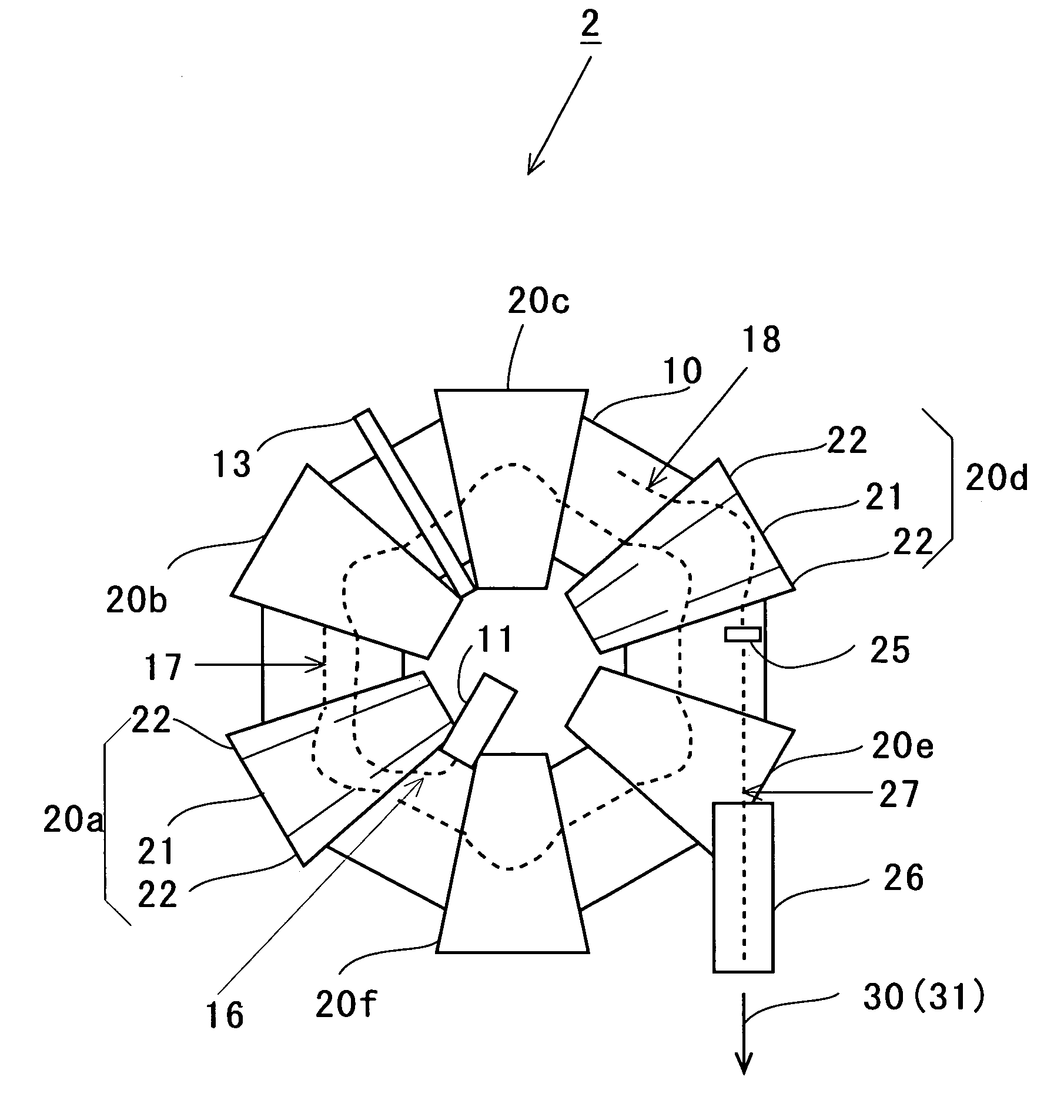
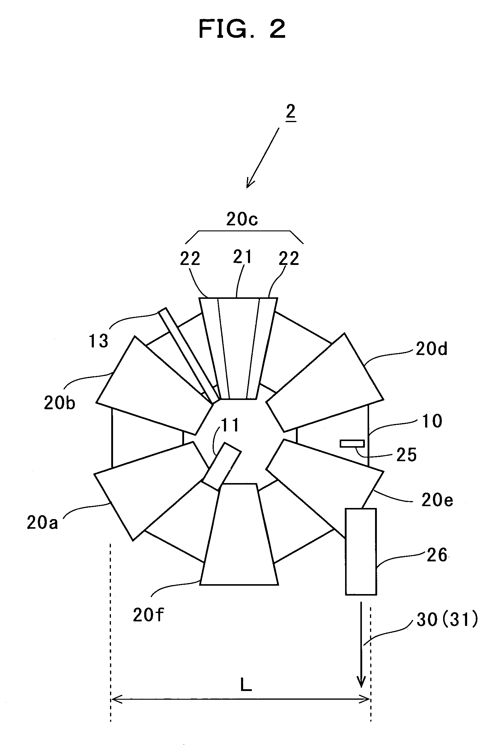
[0075]FIG. 9 is a diagrammatical side view illustrating the makeup of the fixed-field alternating gradient electron accelerator in accordance with the second embodiment of the present invention. The fixed-field alternating gradient electron accelerator 40 in accordance with the second embodiment of the present invention differs from the fixed-field alternating gradient electron accelerator 2 shown in FIG. 7 in that it comprises the first electric magnet for electron beam orbital adjustment 41, the second electric magnet for electron beam orbital adjustment 42, and a beam scanning part 43, and is made up so that electric magnets 20a to 20e are driven by direct current. 27′ shows the electron beam accelerated to 10–15 MeV that is the highest energy. Since all other aspects are same as FIG. 7, explanation is omitted.

[0076]The first electric magnet for electron beam...

third embodiment

[0084]Next a fixed-field alternating gradient electron accelerator in accordance with the present invention is explained.

[0085]FIG. 15 is a diagrammatical side view illustrating the makeup of the fixed-field alternating gradient electron accelerator in accordance with the third embodiment of the present invention. The fixed-field alternating gradient electron accelerator 60 shown here differs from the fixed-field alternating gradient electron accelerator 40 shown in FIG. 9 in that it is provided with an electric magnet 62. Since all other aspects are same as FIG. 9, explanation is omitted. Six electric magnets (62a–62f) are provided in the vacuum container 10.

[0086]FIG. 16 illustrates the makeup of an electric magnet 60 used in the third embodiment, and (a) is a plane view of the electric magnet, and (b) is a cross-sectional view illustrating the makeup of a coil part of the electric magnet. As is shown in FIG. 16(a), the electric magnet 62a is, like the electric magnet 20a, an alte...


PUM


Abstract

A small and light-weighted electron accelerator (2, 40, 60) using a fixed-field alternating gradient of high electron beam intensity is provided with a vacuum container (10), an electric magnet (20) provided in the vacuum container, an electron beam inputting part (11) to input electron beam into the vacuum container (10), an accelerating apparatus (13) to accelerate electron beam, and an electron beam transporting part (26) to transport the accelerated electron beam from the vacuum container (10), and the electric magnet (20) is either an alternating gradient electric magnet made up with a converging electric magnet (21) and divergent electric magnets (22) provided at its both sides, or an alternating gradient electric magnet made up with a converging electric magnet (21) and divergent parts provided at its both sides, and an internal target (25) to generate X-ray is provided inside the vacuum container (10) right before the electron beam transporting part (26), and the accelerated electron beam and X-ray are selectively output. Since the electron beam of more than 10 times the prior cases, 1 to 10 mA at the acceleration voltage of 10 MeV, a radiation medical treatment apparatus (1) can be offered which is capable of irradiating electron beam to cancer organism or others in short time less than 1 / 10 of the prior cases.

Description

[0001]This application is a 371 of PCT / SP03 / 13656 Oct. 24, 2003.TECHNICAL FIELD[0002]The present invention relates to an electron accelerator and radiation medical treatment apparatus using the same, generating electron beam of the energy of several to higher than ten MeV, by fixed-field alternating gradient.BACKGROUND ART[0003]As a radiation medical treatment apparatus for cancer and others using electron beam and X-ray generated therefrom in Prior Art Example 1, a linear accelerator (LINAC) is mainly used at present in which electron is accelerated to the energy of several to higher than ten MeV, for example, Japanese Laid-Open Publication (JP H10-64700A (1998), p. 4, FIG. 1). Also as a linear accelerator, a microtron electron accelerator is known, for example, in the Japanese Laid-Open Publication (JP H07-169600A (1995) pp. 2–3, FIGS. 1 and 2).[0004]FIG. 20 illustrates an example of makeup of a medical treatment linear accelerator of Prior Art Example 1. The medical treatment lin...

Claims


Application Information

Patent Timeline
Patent Type & Authority Patents(United States)
IPC IPC(8): H01J35/08H01J17/22A61N5/10G21K1/02G21K1/093G21K5/04H05H7/10H05H11/00H05H13/08
CPCH05H13/08A61N2005/1089A61N5/10
Inventor MORI, YOSHIHARUAKINE, YASUYUKI
Owner JAPAN SCI & TECH CORP
Why Eureka
Try Eureka