
Electroluminescent (EL) lamp with current limiting fuse

a technology of current limiting fuse and electric lamp, which is applied in the direction of discharge tube luminescnet screen, cathode-ray/electron beam tube circuit elements, instruments, etc., can solve the problems of increased cost, unsuitable external fuse, and high price point of resistor(s), so as to achieve low luminance level, easy adjustment, and high resistance material

Active Publication Date: 2007-03-20
KASEE GEORGE +1
View PDF8 Cites 3 Cited by
  • Summary
  • Abstract
  • Description
  • Claims
  • Application Information

AI Technical Summary

Benefits of technology

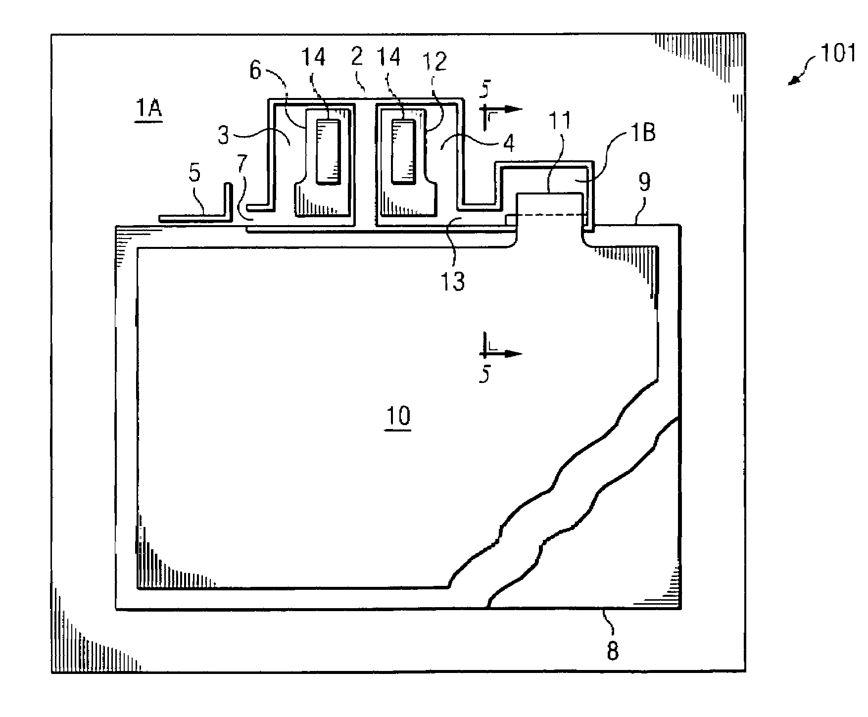
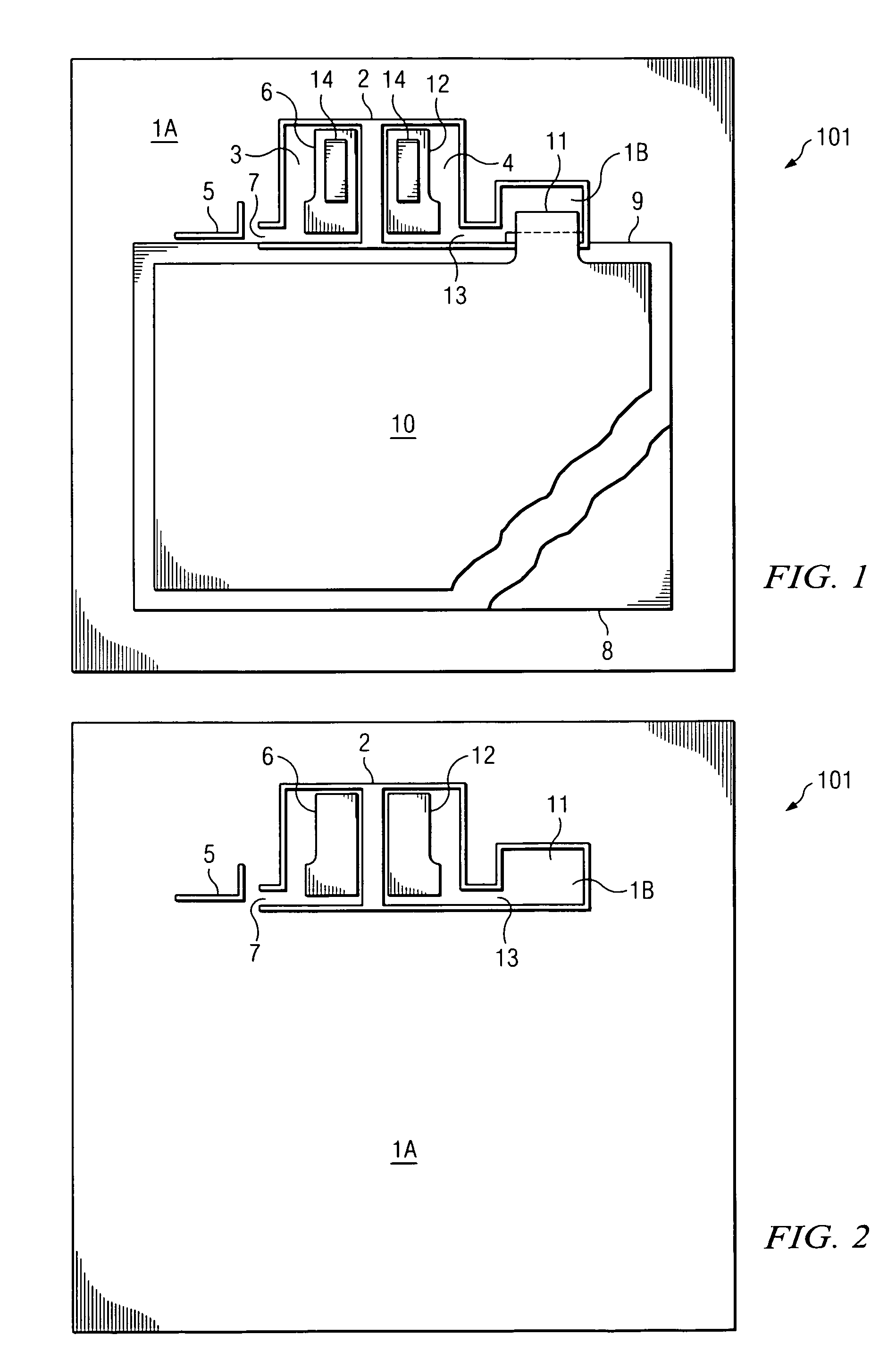
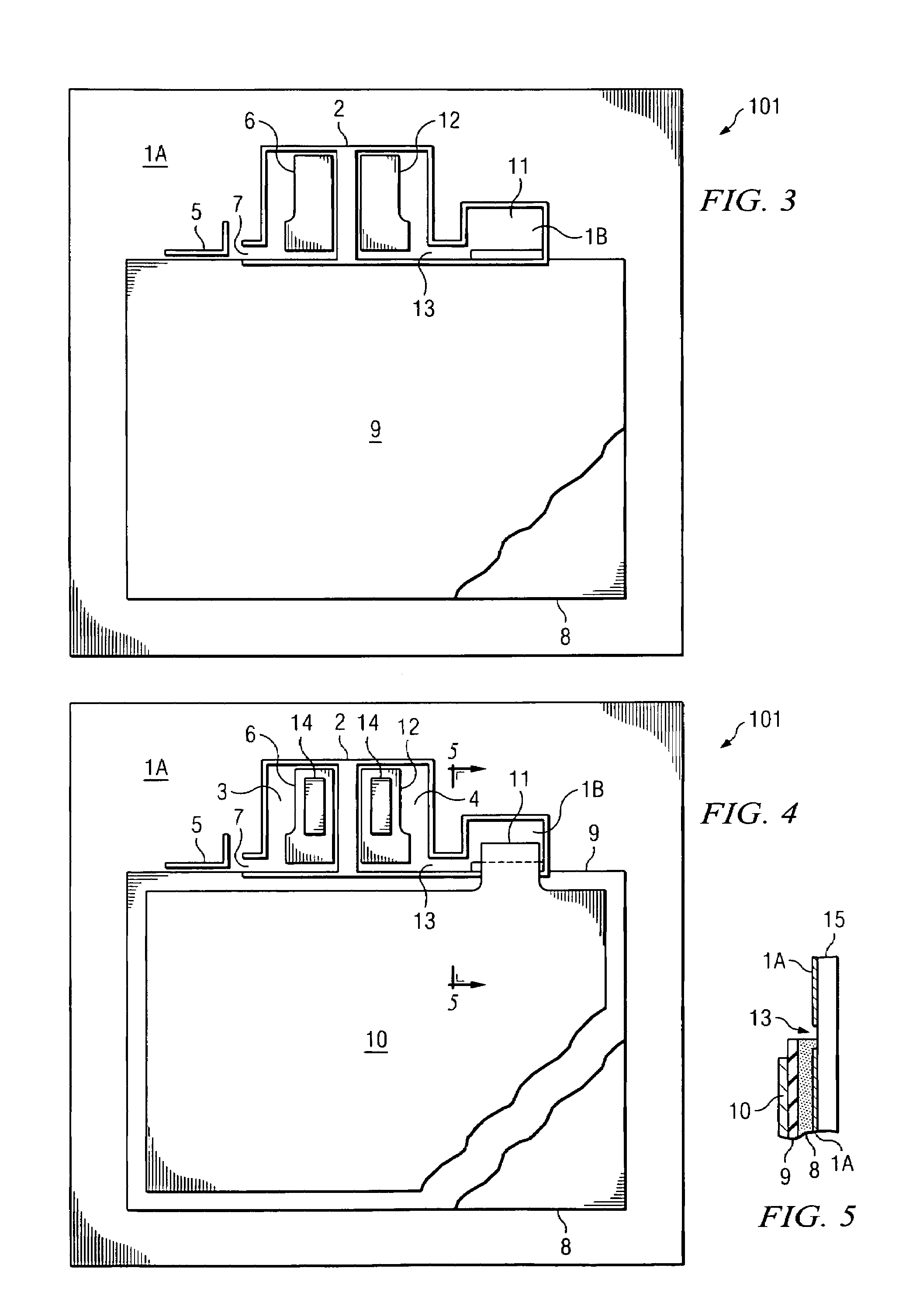
"The present invention provides a method and apparatus to protect an EL lamp from catastrophic destruction initiated by the power source for the EL lamp. The disclosed EL lamp has an equivalent load that is mainly capacitive, two electrodes with a dielectric separation, and a fusible link between the power source and the electrodes. The failure mode of the EL lamp is controlled and safe, with no signs of combustion. The protection provided by the present invention is easily adjustable and can be used for all EL lamp sizes. The failure looks like a non-operating product to the consumer, eliminating the concerns for safety and potential damage to a consumer's dwelling."

Problems solved by technology

An external fuse is not desirable, however, because the failure current needs to be much lower than the known commercial fuses available.
Furthermore, the added costs would make the price point too high for the majority of the market.
Another solution is to add resistance in series with the EL lamp to limit the current available to drive the EL lamp; however, there are two drawbacks to this solution: (1) the cost of the resistor(s) and the interconnect method between the AC power source and EL lamp; and (2) the increased area needed to accommodate the resistor(s).

Method used


Image

  • Electroluminescent (EL) lamp with current limiting fuse
  • Electroluminescent (EL) lamp with current limiting fuse
  • Electroluminescent (EL) lamp with current limiting fuse

Examples


Embodiment Construction

[0017]In one embodiment, blanket deposition of the ITO onto the substrate 15 is followed by selective removal of the ITO according to a desired pattern by means of lasing, chemical etching, abrasive scribing, or other suitable means. Thus, a portion of the front electrode conductor 1 may be removed 2, leaving two sections or islands 3 and 4 of the front conductor with a gap 7 and a gap 13 of a certain width to conduct current from inside the islands to outside for powering the front and back electrodes of the EL lamp 101. In another embodiment, ITO is selectively deposited onto the substrate 15, such as by painting or screen-printing or other suitable means, only in desired areas to form a desired pattern. This provides a cost-saving benefit by conserving resources, and avoiding unnecessary waste of ITO that would otherwise be removed.

[0018]The front electrode input power contact area 6 and the back electrode input power contact area 12 may be printed on the conductive substrate wit...


PUM

PropertyMeasurementUnit
resistanceaaaaaaaaaa
electroluminescent lampaaaaaaaaaa
electrically conductiveaaaaaaaaaa

Abstract

An electroluminescent (EL) lamp having at least two integral fusible links and a method of manufacturing such a lamp are disclosed. The present invention provides for a fusible link between the front electrode input power contact area and the transparent electrode. In addition, the present invention provides a second fusible link between the back electrode input power contact area and the transparent electrode. The fusible links are designed to become non-conductive (open) if a certain current level is exceeded. The EL lamp fails in a controlled way, without signs of combustion. The EL lamp is therefore protected from self-destruction when subject to an anomaly or manufacturing defect.

Description

FIELD OF THE INVENTION[0001]The present invention relates generally to electroluminescent (EL) lamps, and more particularly, to an improved electroluminescent lamp having at least two fusible links.BACKGROUND OF THE INVENTION[0002]EL lamps are typically formed by depositing a number of layers onto a transparent substrate. The layers typically include the transparent substrate, a transparent front electrode, a phosphor layer, two or more dielectric layers, and a rear electrode. Various other layers are often included. When an alternating electric current is applied to the two electrodes, a field is developed, and the phosphor layer emits light. One example of an EL lamp is a night light.[0003]EL lamps powered directly from the AC line, such as standard 120 vrms / 60 Hz house power, are susceptible to voltage surges that could breakdown the dielectric insulator used to separate the front and back electrodes of the EL lamp. Surges, also referred to as anomalies, are short duration high v...

Claims


Application Information

Patent Timeline
Patent Type & Authority Patents(United States)
IPC IPC(8): H01H69/02G08B21/00
CPCH01H69/022H01H85/0241H05B33/28H01H85/046Y10T29/49107
Inventor SANDERSON, STEPHEN JAYSTILES, STEPHEN RAY
Owner KASEE GEORGE
Learn More