
High speed machining device

a high-speed machining and tool technology, applied in the field of machining, can solve the problems of increasing the weight of parts, increasing the cost and assembly time, and requiring additional machining time for low-speed machining with current right-angle head designs, and achieves the effects of high horsepower, substantial material removal, and high speed

Inactive Publication Date: 2007-03-20
THE BOEING CO
View PDF10 Cites 16 Cited by
  • Summary
  • Abstract
  • Description
  • Claims
  • Application Information

AI Technical Summary

Benefits of technology

The present invention provides an air turbine driven rotary machine tool that is small, high-speed, and has a large machining bit. The tool has a stator and rotor with blades that are aligned, and an annular cavity for supplying air to the blades. The tool also has a cylindrical spindle for rotating a bit, and a pressurized air supply source for the blades. The tool support controls the speed of rotation of the spindle. The invention also includes an annular exhaust cavity and exhaust openings for air to flow through. The technical effects of the invention are improved efficiency, speed, and power, as well as reduced space requirements.

Problems solved by technology

Some of these tools are bulky and operate at a relatively low speed and high horsepower.
The sheet metal requires additional fasteners, which in turn increase the part weight, part count, cost and assembly time.
Low speed machining with current right angle head designs requires additional machining time and access to confined areas is limited by the bulkiness of the head.
This requires more setup time, machining time, and increases tooling costs.
The bulkiness of current right angle heads limits their capability.

Method used


Image

  • High speed machining device
  • High speed machining device
  • High speed machining device

Examples


Embodiment Construction

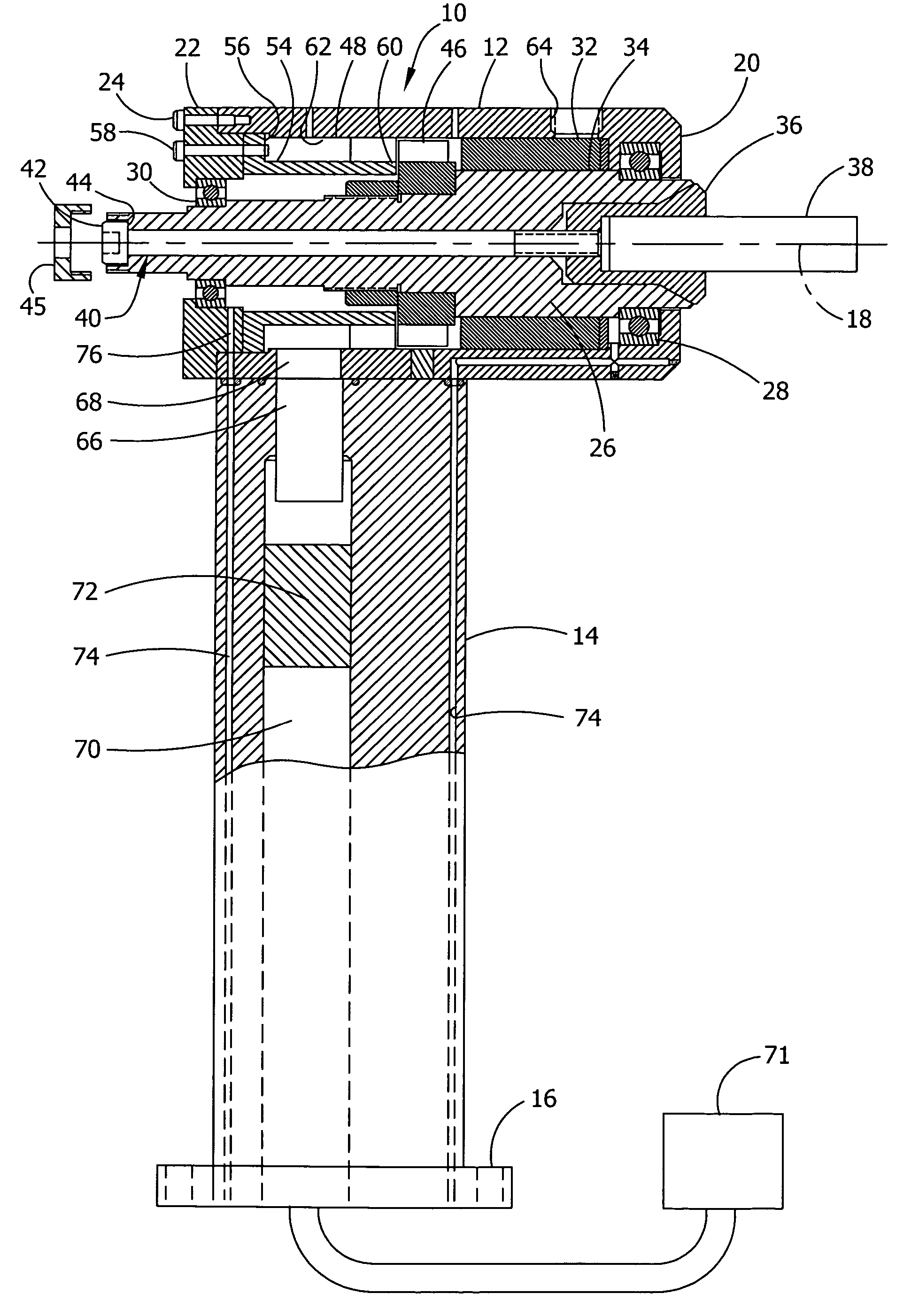
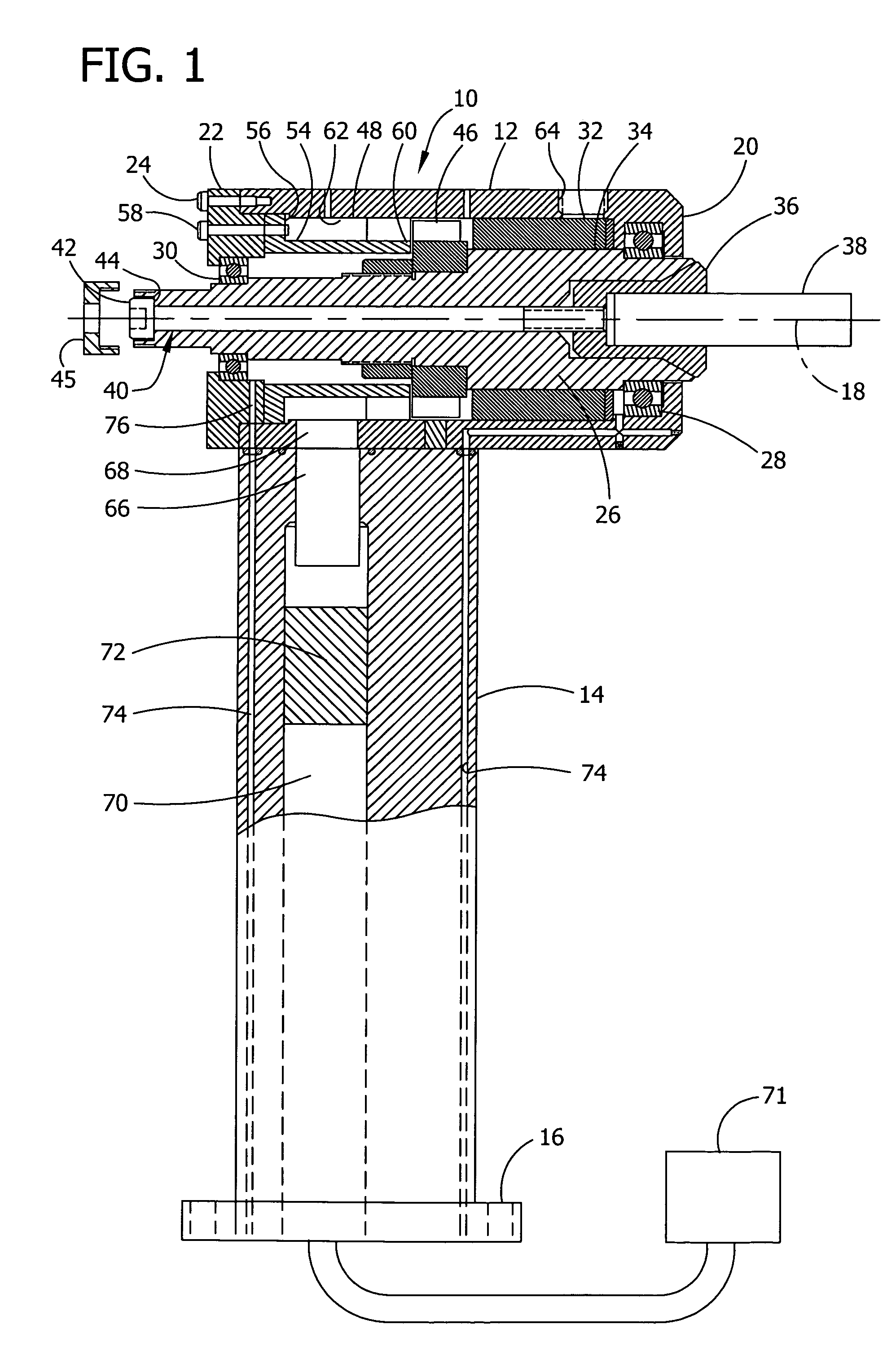
[0019]A preferred embodiment of the turbine driven rotary machine tool, designated generally as 10, is shown in partial cross-section in FIG. 1. Machine tool 10 has a tool casing 12 of generally cylindrical form and which contains the main operating parts of the machine tool. A tool support 14 is secured to the tool casing 12 so that the machine tool 10 can be attached to a machine tool spindle (not shown) at its outer end 16 for being moved into position relative to a work piece and for making cuts on the work piece in a well known manner.

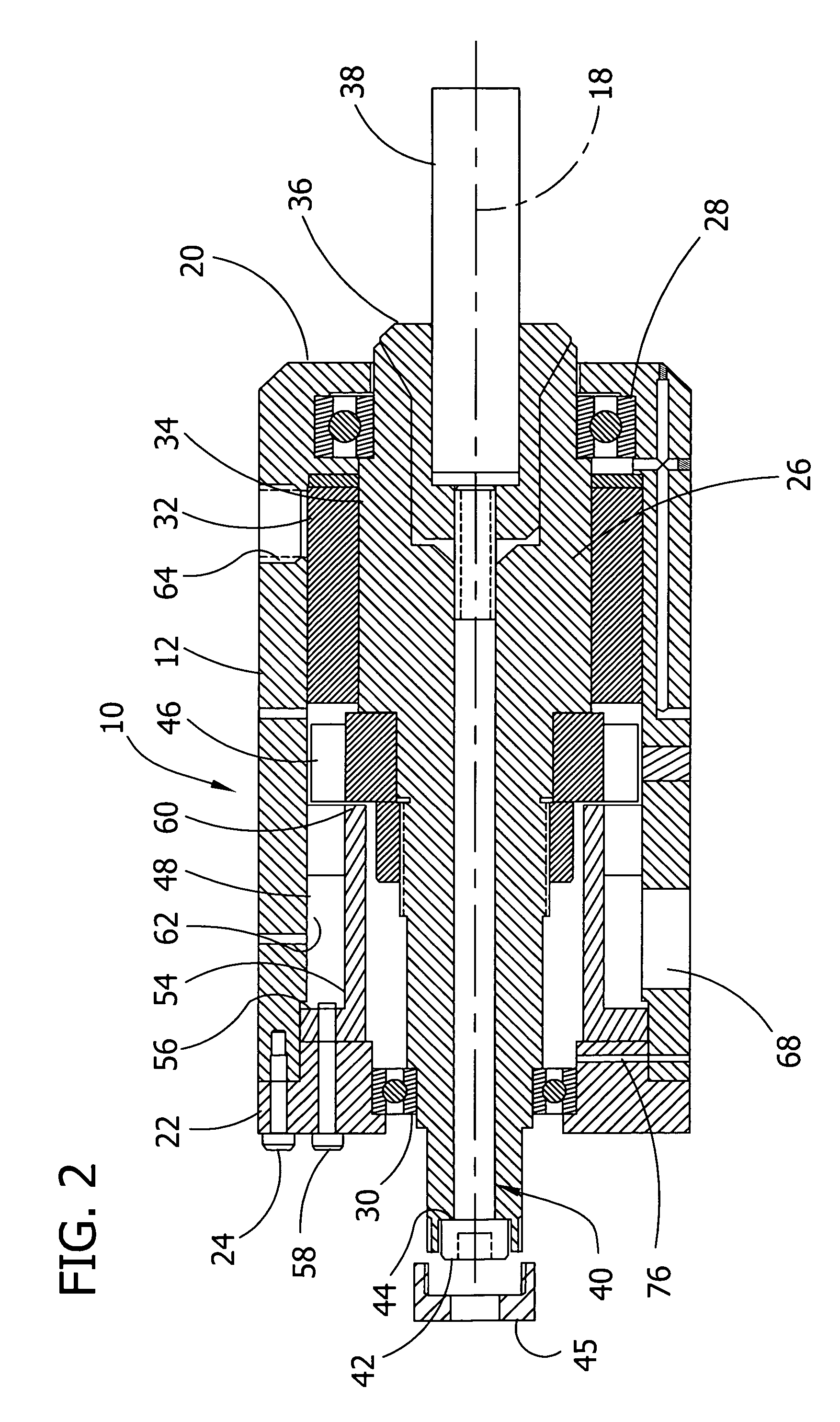
[0020]Tool casing 12 is generally cylindrical and has a central longitudinal axis 18 and a closed front end 20 formed as part of the tool casing. A rear cap 22 is bolted to the opposite end of tool casing 12 by a series of bolts 24. Mounted within the tool casing 12 is a spindle 26 which is supported in the front end of the casing by bearing 28 and in the rear cap by bearing 30. An additional cylindrical ceramic bearing 32 is mounted in the tool c...


PUM


Abstract

An air turbine driven rotary machine tool having a tool casing, a turbine rotor mounted within the casing for rotation, a stator mounted in fixed position in the tool casing coaxially aligned with the turbine rotor, a annular cavity defined within the casing and coaxially aligned with the stator and rotor for supplying air to the stator blades, a cylindrical spindle coaxially mounted with the turbine rotor in the tool casing for rotation with the turbine rotor, and a tool holder mounted coaxially to the spindle for rotation therewith and having an end thereof for operably receiving a cutting tool.

Description

FIELD OF THE INVENTION[0001]The present invention is related to the field of machining, and more particularly, to high speed machining tools.BACKGROUND OF THE INVENTION[0002]There currently exist several turbine driven rotary machine tools for various operations. Some of these tools are bulky and operate at a relatively low speed and high horsepower. These tools can use large cutting bits for removing substantial amounts of material from a work piece. There exists other turbine driven rotor machine tools that are relatively less bulky and operate at a relatively high speed with small cutting bits to remove lesser amounts of material at a relatively high rate.[0003]As a matter of example, currently, complex aerospace parts containing T-stiffners and return flanges that carry around corners of a pocket are designed as sheet metal attachments or machined with a low speed rotary machine tool having a right angle head. The sheet metal requires additional fasteners, which in turn increase...

Claims


Application Information

Patent Timeline
Patent Type & Authority Patents(United States)
IPC IPC(8): F01D1/04B23Q5/06
CPCB23Q5/06Y10S415/904
Inventor HELVEY, AMY M.YOUNG, KEITH A.TLUSTY, LEGAL REPRESENTATIVE, HANAWAYMACK, KEVINTLUSTY, DECEASED, JIRI
Owner THE BOEING CO
Learn More