Systems for drying moisture-containing work pieces and methods for drying same

a technology for drying systems and work pieces, applied in the direction of manufacturing tools, lighting and heating apparatus, furnaces, etc., can solve the problems of preventing the operation of two fans in either a full exhaust or a partial exhaust, causing the loss of circulation air, and causing the loss of moisture. , to achieve the effect of reducing drying time, preventing the loss of circulation air, and reducing energy costs

Active Publication Date: 2007-03-27
AMERICAN WOOD DRYERS LLC
View PDF6 Cites 29 Cited by
  • Summary
  • Abstract
  • Description
  • Claims
  • Application Information

AI Technical Summary

Benefits of technology

[0010]A method is also provided of controlling the system of this invention to have it operate in a way that the kiln will only ventilate the amount of humidified air required to maintain the system at steady state operating conditions. This can be accomplished by conducting dry kiln operation at any level from 0 to 100% of the required output, and being able to sustain the dry kiln operation at that predetermined output level.
[0011]Unlike U.S. Pat. No. 4,662,083, the subject system describes independently controlled intake / exhaust fans in which the speed of each fan can be independently varied to correct pressure imbalances in the kiln. For example, imbalances in the kiln can be corrected by having the speed of the intake fans to run at a different speed than the exhaust fans. Also, the fan speeds can be varied in the system of the present invention to either increase or decrease the amount of venting required. This fan speed variability allows for much finer and therefore much more efficient operation. The system of this invention can also include various temperature sensors that measure cool outside air temperature, temperature of that air entering the heat exchanger, temperature of air entering the heat exchanger from the building and temperature of the air as it leaves the heat exchanger. All of this information is used by the controller to adjust the fan speed and direction which achieves efficient operation of the kiln.
[0012]The subject system has a unique reversible heat exchanger that is designed to allow the air flow through the heat exchanger to switch directions based on a predetermined dry kiln air flow direction. This heat exchanger preferably has independent air flow channels that allow the hot moist air flow to pass on one side of a transfer surface and for the cool dry air flow to pass on the other side of the surface. Typically, each respective air flow can be heated without mixing. When the airflow in the dry kiln is reversed, the airflow through the heat exchanger channels is preferably also reversed. Reversible fans can be employed that have substantially the same airflow characteristics in both directions control the airflow through the heat exchanger. By reversing the airflow through the heat exchanger, any auxiliary equipment, such as ducting or the like, that would be required to deliver the air to the kiln can be avoided. Furthermore, the use of switching dampers that are required to be synchronized with the airflow in a conventional dry kiln can be eliminated.
[0015]The power vent heat exchanger system is preferably located on top of the dry kiln over the main kiln circulation fans. This eliminates the need for distribution ducting inside of the dry kiln. Each dry kiln can preferably have one or more of these systems depending on the capacity of the venting requirements.
[0016]The power venting and heat recovery system of the dry kiln is designed to significantly reduce the energy cost by providing optimal kiln heat recovery. The system extracts heat out of the hot moist air that is exhausted from the kiln during the venting process. The heat is then added back into the cool dry air that is introduced back into the dry kiln during this venting process. It also reduces drying time by preventing the loss of circulation air. This ensures consistent air velocity through the lumber load during heavy venting for greater product uniformity.
[0018]A multi-directional air flow heat exchanger is employed for (a) receiving heated humidified air and atmospheric air, and (b) for recycling waste heat from exhaust air from the drying compartment, and (c) for heating the atmospheric air in the heat exchanger using recovered heat extracted from the heated humidified air to a temperature higher than ambient temperature. In this way, energy costs and drying time are reduced, and the loss of circulation air is prevented. The heat exchanger preferably has first and second air flow channels that allow hot moist air flow to pass on a first side of a transfer surface and for the cool dry air flow to pass on a second side of the transfer surface.

Problems solved by technology

This injected heat will cause the lumber to release additional moisture.
This precludes allowing the two fans to operate in either a full exhaust mode or a full intake mode.

Method used


Image

  • Systems for drying moisture-containing work pieces and methods for drying same
  • Systems for drying moisture-containing work pieces and methods for drying same

Examples


Embodiment Construction

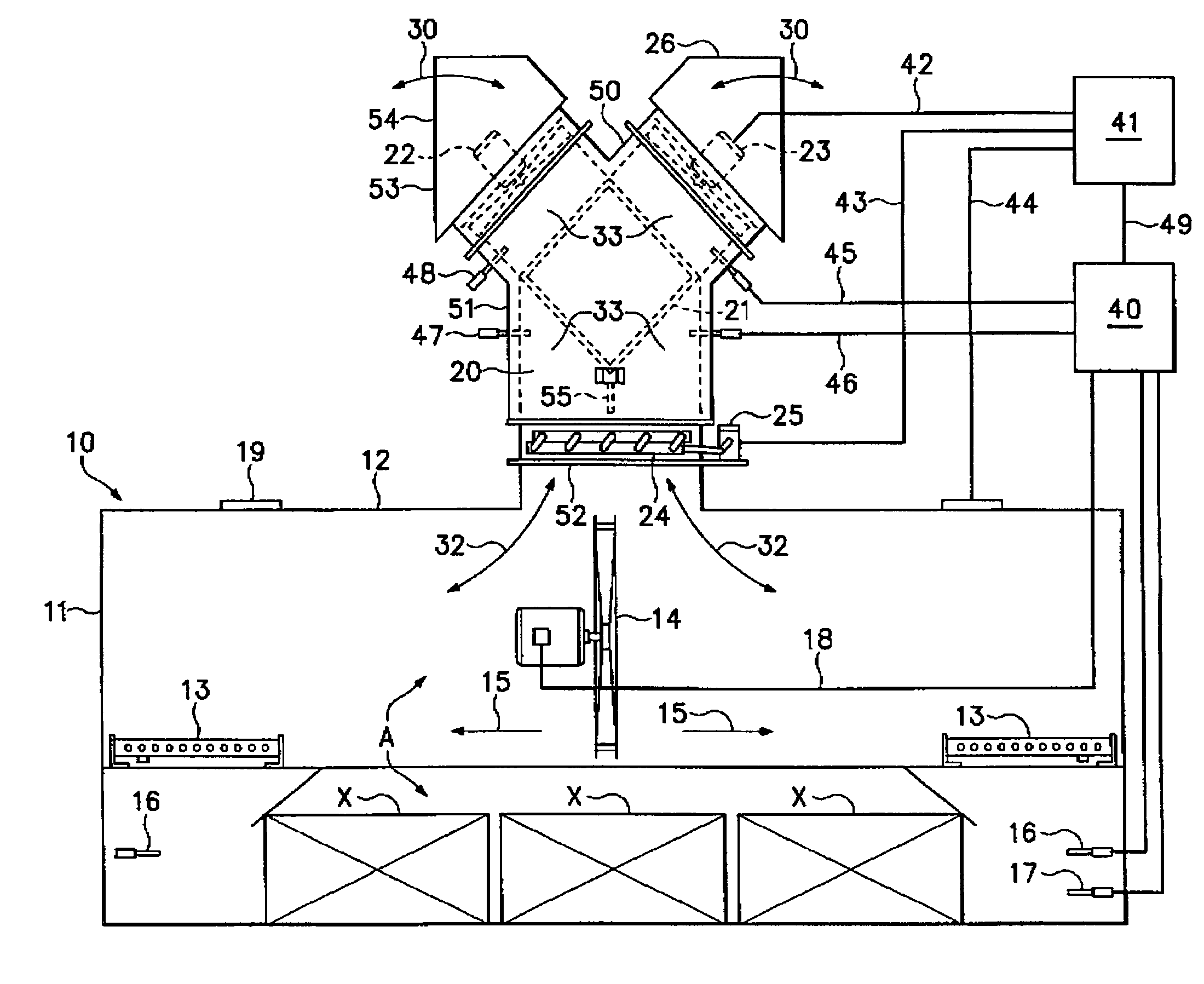
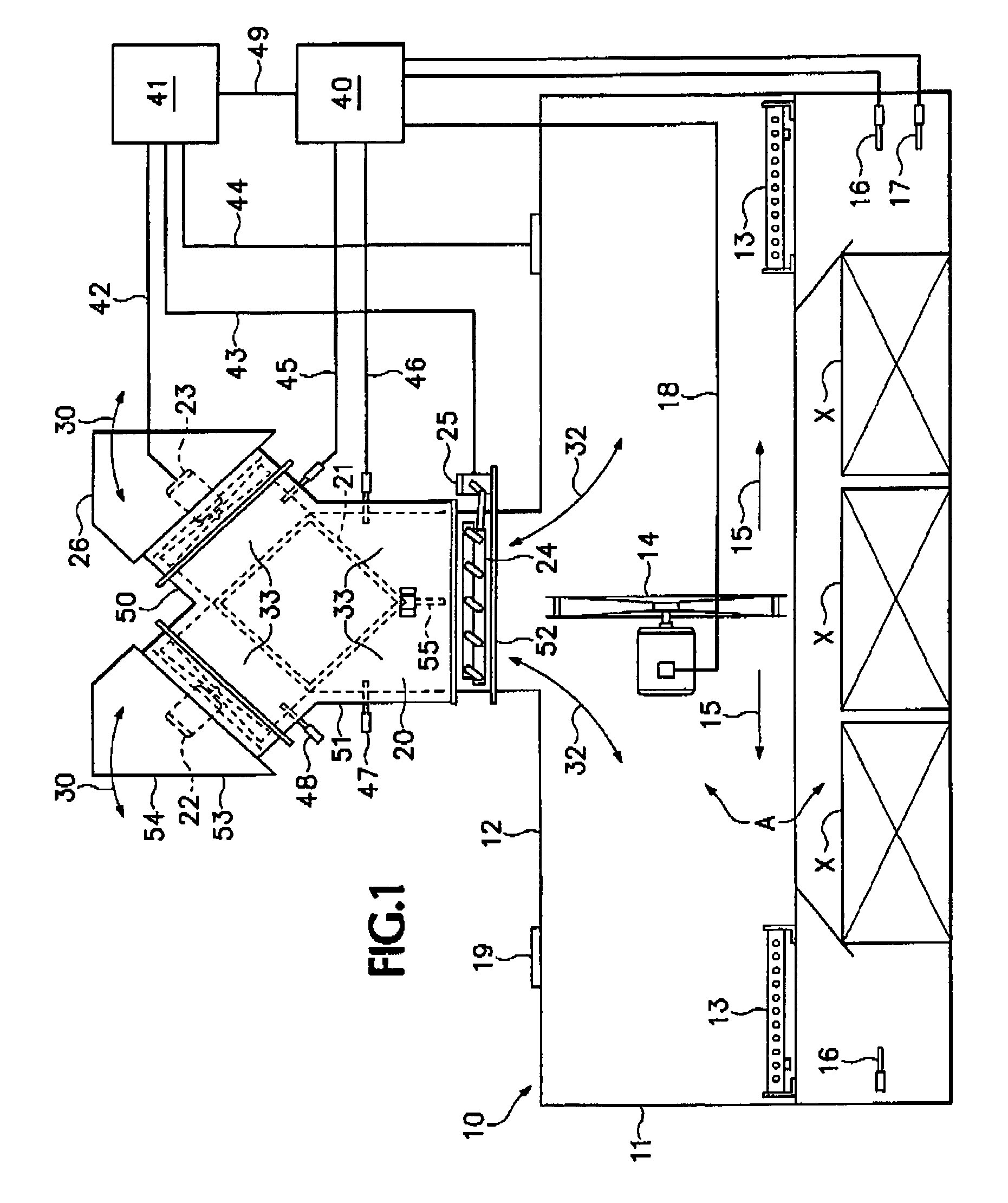
[0025]Referring now to FIG. 1, a diagrammatic representation of a system 1 is provided which is employed in combination with a building 10, having enclosing walls 11 and roof 12, for controllably drying moisture-containing work pieces “X”. System 1 is typically a power venting heat recovery system 20 and the associated programmable controller system 41, which is preferably a programmable logic controller system. System 1 can be a ThermoVent System manufactured by American Wood Dryers, Inc. of Clackamas, Oreg.

[0026]Work pieces “X” are typically lumber which is dried employing heating system 13, which is typically a conventional kiln heating system. Heating system 13 is located within the building 10 and is in communication inline with an air circulation system 14, which is typically a conventional kiln dryer circulation system. Air circulation system 14 is designed to move air over the work pieces X located in a workspace “A” in the building 10. The air circulation system 14 can reve...


PUM


Abstract

A system and method are provided for controllably drying moisture-containing work pieces. The system comprises a drying compartment defining an internal workspace for housing and drying the moisture-containing work pieces by introducing heat into the internal workspace and heating the moisture-containing work pieces located in the internal workspace by removing heated moisture from the work pieces and absorbing the heated moisture into the air in the workspace to produce heated humidified air. A multi-directional air flow heat exchanger is employed for receiving heated humidified air and atmospheric air and for recycling waste heat from exhaust air from the drying compartment, and for heating the atmospheric air in the heat exchanger using recovered heat extracted from the heated humidified air to a temperature higher than ambient temperature thereby reducing energy costs and drying time and preventing the loss of circulation air. First and second reversible variable speed fans are also included in the system. Each of the fans is independently controllable at respective intake and exhaust modes and at variable air flow rates, without employing a damper for controlling the flow of exhaust air and atmospheric air to and from the heat exchanger.

Description

BACKGROUND OF THE INVENTION[0001]The present invention relates generally to systems for drying of moisture-containing work pieces, such as lumber or the like, and to methods for drying same, particularly, to ventilation systems and methods for drying the work pieces, and more particularly, to ventilation systems used in conjunction with kilns and methods for drying work pieces such as lumber.[0002]Drying of moisture-containing work pieces, such as lumber, is known. For example, during the kiln drying process of lumber, heat is injected into the internal workspace of the kiln to remove a substantial amount of moisture from the lumber located therein. The moisture removal rate from the lumber is controlled by setting the kiln dry bulb and the corresponding kiln wet bulb temperatures at specified values. These temperatures are determined by the drying schedule selected by the kiln operator. As the lumber dries, moisture is absorbed into the kiln atmosphere which in turn raises the wet ...

Claims


Application Information

Patent Timeline
Patent Type & Authority Patents(United States)
IPC IPC(8): F26B21/00F26B21/06F26B21/08B27K5/00F26B3/04F26B19/00F26B21/02F26B21/04F26B21/12F26B23/00F26B25/06
CPCF26B21/026F26B23/002F26B21/12F26B2210/16Y02P70/10
Inventor KOLARI, GARY L.
Owner AMERICAN WOOD DRYERS LLC
Why Eureka
Try Eureka